How is load duration controlled with Rapid Load Testing?
Load duration in a rapid load test is controlled primarily through the design of the drop mass and, where applicable, the buffer or spring system placed between the falling weight and the pile head. The load pulse must last long enough to suppress stress wave propagation effects inside the pile, allowing the pile to behave approximately as a single moving body during the test. The sections below unpack each factor that shapes this control, from buffer mechanics to measurement practice and the differences between Statnamic and StatRapid systems.
What factors determine load duration in Rapid Load Testing?
Load duration in a rapid load test is determined by the interaction between the drop mass, the stiffness of any buffer or spring system, and the dynamic properties of the pile itself. The governing criterion is that the force pulse must last long enough relative to the time a stress wave needs to travel the full length of the pile and return. When this condition is met, stress wave effects inside the pile are strongly reduced and the pile can be treated as a concentrated mass for analysis purposes.
ISO 22477-10:2016 formalizes this by relating the required load duration to pile length and the stress wave propagation velocity through the pile material. NEN 7201:2025 applies the same fundamental distinction. In practice, several variables interact to produce the final pulse length:
- Drop mass: A heavier falling weight stores more energy and, combined with a buffer, produces a longer force pulse.
- Buffer or spring stiffness: A softer buffer spreads the impact over a longer time window, directly extending the load duration.
- Pile length and wave speed: Longer piles require longer pulses to keep stress wave effects negligible.
- Pile diameter and surrounding soil shear wave velocity: Research by Matsumoto highlights that wave and relaxation phenomena also occur in the soil around a friction pile, meaning the required duration is not determined by pile geometry alone.
Because these factors interact, load duration cannot be fixed by a single rule of thumb. It must be evaluated for each specific pile-soil combination before the test is designed.
How does buffer design affect the load pulse shape?
The buffer placed between the falling mass and the pile head is the primary tool for shaping the load pulse in a rapid load test. A stiffer buffer produces a shorter, sharper pulse, while a softer buffer spreads the impact energy over a longer time, creating a smoother and more extended force curve. Selecting the right buffer stiffness is therefore a direct way to control whether the test meets the load duration requirements for Rapid Load Testing.
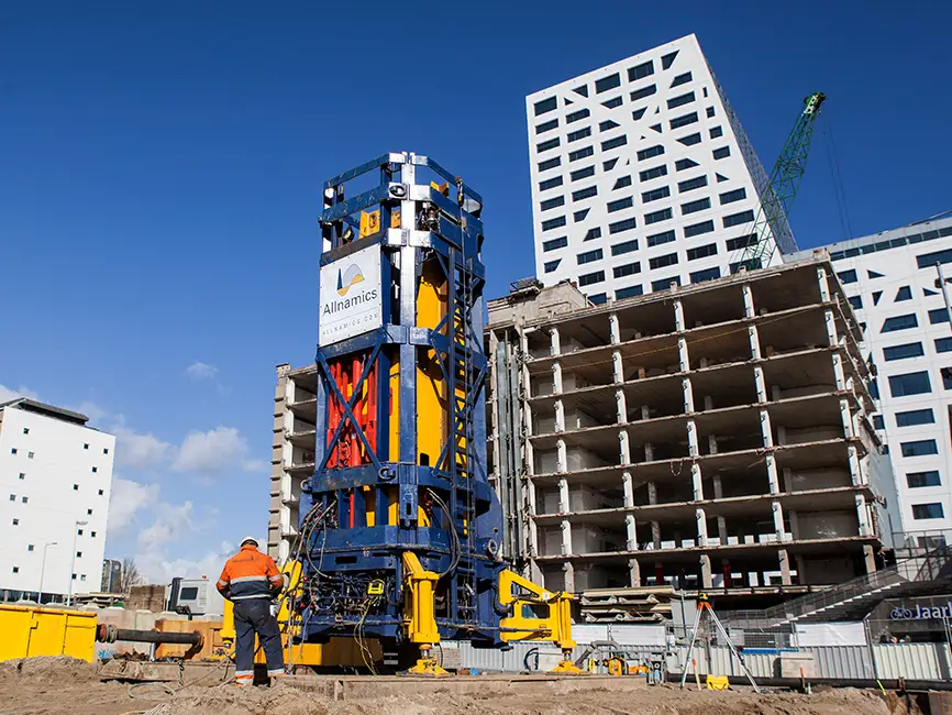
In the StatRapid system, the buffer is a purpose-designed spring package. When the drop weight strikes this package, the original impact is distributed across a longer contact period. This is the mechanism that distinguishes StatRapid from a conventional drop-weight dynamic test: the spring package converts what would otherwise be a high-frequency impact into a force pulse with a duration that falls within the Rapid Load Testing range.
Buffer design also influences the peak force applied to the pile. A softer buffer reduces peak stress at the pile head, which can be an advantage when testing cast-in-place concrete piles where high impact stresses are a concern. The trade-off is that a very soft buffer may not generate sufficient peak force to mobilize the pile’s full resistance. Buffer selection therefore balances pulse duration, peak force, and pile head stress simultaneously.
What is the target load duration range for Rapid Load Testing?
The target load duration for a rapid load test is typically in the range of approximately 100 to 200 milliseconds, though the exact value depends on pile length and wave speed. The defining requirement is that the duration must be long enough to move the test outside the domain of a conventional impact test, where stress wave behaviour dominates, while remaining short compared to a static load test. ISO 22477-10:2016 and NEN 7201:2025 both use this wave-travel-time criterion as the boundary condition.
A useful way to think about the lower boundary is the two-way travel time of a stress wave through the pile: the load pulse should last considerably longer than the time it takes a wave to travel from the pile head to the toe and back. For a concrete pile with a wave speed of around 3,800 to 4,000 metres per second, this two-way travel time is relatively short for piles of typical length, which is why even a pulse of 100 milliseconds can satisfy the criterion for many practical pile lengths.
The upper boundary is less rigidly defined but is set by the requirement that the test remains distinct from a static load test. In practice, the load duration is chosen to suit the specific pile and soil conditions rather than to hit a universal target number. For friction piles in particular, the surrounding soil’s shear wave velocity may also influence what duration is needed to adequately capture soil behaviour during the test.
How is load duration verified and measured during a test?
Load duration is verified by measuring the force-time history at the pile head during the test using calibrated load cells. The recorded force signal shows the complete shape of the load pulse, from the moment force begins to build until it returns to zero. Engineers review this record to confirm that the pulse length meets the wave-travel-time criterion for the pile being tested.
Displacement and velocity are measured simultaneously, typically using accelerometers and displacement transducers mounted at or near the pile head. These measurements serve two purposes: they allow the inertia correction to be applied during analysis, and they provide an independent check on the dynamic behaviour of the pile during the test. Together, the force and motion records form the complete dataset needed for interpretation using methods such as the Unloading Point Method.
Verification is not limited to post-test review. In practice, the test setup is designed in advance based on the pile geometry and expected soil conditions, so the engineer can predict whether the chosen drop mass and buffer combination will produce a pulse of the required duration. If the first test drop produces a pulse that is too short, the buffer stiffness can be adjusted before subsequent drops. This iterative approach is part of standard practice under both ISO 22477-10 and NEN 7201:2025, both of which treat execution and analysis as specialist activities requiring geotechnical expertise.
What happens if load duration is too short or too long?
If the load duration is too short, the test moves into the domain of Dynamic Load Testing rather than Rapid Load Testing. Stress wave effects inside the pile become significant, the pile no longer behaves as a single moving body, and the simpler inertia correction used in Rapid Load Testing analysis is no longer valid. The measured response then requires the more complex stress wave analysis methods associated with dynamic testing, and the results cannot be interpreted as a rapid load test.
If the load duration is too long, the test approaches static loading conditions. While this might seem harmless, it creates a different problem: the rate-dependent soil behaviour that Rapid Load Testing accounts for through correction methods may no longer be consistent with the assumptions built into those methods. The analysis model must match the actual loading regime, and a pulse that is significantly longer than intended may fall outside the validated range of the interpretation approach being used.
There is also a practical consequence when the pile is not loaded far enough to mobilize failure. If the test does not reach the pile’s resistance limit, the maximum measured force cannot simply be extrapolated to a static capacity. NEN 7201:2025 sets explicit restrictions on this for certain load test classes, and the same caution applies regardless of whether the duration issue is the primary concern. A test that fails on duration criteria and also fails to mobilize failure provides very limited usable information.
How does load duration control differ between Statnamic and StatRapid testing?
Statnamic and StatRapid both belong to the Rapid Load Testing category and share the same fundamental objective: generating a force pulse long enough to suppress stress wave effects in the pile. The difference lies in how each system produces that pulse, which in turn affects how load duration is controlled in practice.
In a Statnamic test, a reaction mass is accelerated upward by a rapid build-up of pressure, and the reaction to this acceleration applies a downward force on the pile. The duration of the load pulse is governed by the mass of the projectile and the pressure-time profile of the propellant charge. Adjusting the charge characteristics and projectile mass are the primary controls available to the engineer.
In a StatRapid test, a drop weight falls onto a spring package placed at the pile head. The spring package absorbs the impact and redistributes it over a longer time window. Load duration is controlled by selecting the appropriate spring stiffness and drop height. A softer spring package produces a longer pulse; a stiffer one shortens it. This mechanical approach gives the engineer a direct and repeatable way to tune the pulse shape before and between test drops.
NEN 7201:2025 explicitly distinguishes between these two execution principles. Both are valid forms of Rapid Load Testing, and both require the same verification: the recorded force-time history must confirm that the pulse duration satisfies the wave-travel-time criterion for the pile under test. The analysis methods applied after the test are the same regardless of which system generated the pulse.
How We Support Rapid Load Test Design and Execution
Controlling load duration correctly requires more than selecting a drop mass and buffer. It demands a thorough understanding of the pile geometry, soil conditions, applicable standards, and the interaction between test setup and analysis method. This is where our team adds direct value.
When you work with us on a rapid load test programme, we provide:
- Pre-test design and pulse prediction: We calculate the required load duration for your specific pile and soil conditions and select the appropriate equipment configuration to achieve it.
- On-site execution and real-time monitoring: Our specialists verify the force-time record during testing and adjust the setup if the initial drops do not produce the intended pulse shape.
- Interpretation using validated methods: We apply the Unloading Point Method and other recognized analysis approaches, including rate-effect corrections appropriate for your soil type, to convert the measured rapid load response into a reliable static equivalent capacity.
- Compliance with ISO 22477-10, NEN 7201:2025, and ASTM D7383: We ensure the test design, execution, and reporting meet the requirements of the applicable standard for your project jurisdiction.
- StatRapid equipment and expertise: As developers of the StatRapid system, we bring direct knowledge of how spring package design affects pulse shape and how to optimize the setup for your pile type.
If you are planning a foundation testing programme and want to confirm that Rapid Load Testing is the right method for your project conditions, contact our team to discuss your pile type, soil profile, and load requirements.
Related Articles
- Is pile head preparation required for Rapid Load Testing?
- Is there a Rapid Load Testing code for the Netherlands?
- What challenges does saltwater exposure create for testing equipment?
- What is a reaction system in static pile load testing?
- What is the difference between static and dynamic pile load testing?