

How are maximum compression stresses predicted during pile driving?
Maximum compression stresses during pile driving are predicted using one-dimensional stress wave analysis, which simulates how a hammer impact travels through a pile as a wave and interacts with the surrounding soil. The governing principle is that every hammer blow generates a compressive stress wave that propagates downward through the pile, and the peak magnitude of that wave determines the maximum compression stress the pile experiences. Engineers use dedicated software to model the complete hammer-pile-soil system and calculate these stresses at every depth and every blow throughout the installation sequence.
Accurate prediction matters because a pile can physically reach its target depth while simultaneously developing stresses that exceed the material’s allowable limits, causing damage that is difficult or impossible to detect after installation. The sections below address the most common questions engineers raise when planning a drivability study.
What methods are used to predict compression stresses in driven piles?
Compression stresses in driven piles are predicted using wave equation analysis, a numerical method that models the pile as a series of discrete mass-spring elements and simulates how a hammer impact propagates through the pile as a stress wave. The analysis calculates force, velocity, and stress at every point along the pile for each blow, producing a complete picture of compression and tension stress development during installation.
The wave equation approach replaced earlier empirical pile-driving formulas because it captures the dynamic nature of the driving process rather than treating the hammer blow as a static force. Modern implementations, such as AllWave-PDP for impact driving and AllWave-VDP for vibratory driving, solve the wave equation using the Method of Characteristics, which tracks stress wave propagation and reflection in both directions along the pile simultaneously.
The analysis requires three coupled models working together: a hammer model that generates the impact force-time history, a pile model that describes the geometry and material properties, and a soil model that defines resistance along the shaft and at the pile toe. Together, these models allow engineers to predict not just whether a pile will reach its target depth, but what compression stresses it will experience at every stage of installation.
How does wave equation analysis calculate pile compression stresses?
Wave equation analysis calculates pile compression stresses by simulating the propagation of a stress wave from the hammer impact downward through the pile, tracking how that wave interacts with soil resistance and reflects at boundaries. The peak compressive stress at any cross-section equals the maximum force passing through that section divided by the pile’s cross-sectional area, and the analysis captures this value at every node along the pile for every blow.
The core sequence follows a clear physical logic: a hammer impact generates a force-time history; that force enters the pile head as a downward-traveling compressive wave; the wave loses energy to shaft friction as it travels; and it partially reflects at the pile toe. The reflected wave travels back upward and can interact with subsequent downward waves, creating complex stress distributions that simple static calculations cannot capture.
A critical insight from stress wave theory is that the rated energy of a hammer is not the same as the energy delivered to the pile. Cushion properties, hammer efficiency, and the stiffness of the pile-soil system all affect how much energy actually enters the pile and in what form. A stiffer cushion, for example, produces a shorter, higher-amplitude pulse, which increases peak compression stress even if the total energy remains the same. This is why the hammer model must describe the actual impact force-time history rather than simply assigning a nominal energy value.
For concrete piles, the analysis also tracks stresses in the reinforcement and prestressing steel separately, and advanced models can simulate crack formation when tensile strength is exceeded, including the change in cross-sectional impedance that cracking causes.
What factors most influence maximum compression stress during driving?
The maximum compression stress a pile experiences during driving is most strongly influenced by hammer energy and impact velocity, cushion stiffness, pile impedance, and the magnitude of soil resistance at the toe. Each of these factors shapes either the amplitude of the incoming stress wave or the magnitude of the wave reflected back from the pile toe.
The following factors deserve particular attention in any drivability study:
- Hammer selection: A heavier or more energetic hammer increases the amplitude of the compressive wave entering the pile. Selecting a larger hammer to overcome difficult soil conditions can simultaneously push compression stresses beyond allowable limits.
- Cushion properties: The elastic modulus and coefficient of restitution of the cushion material directly control the shape and peak of the force pulse. A softer cushion reduces peak stress but also reduces energy transfer efficiency. For wooden cushions, the properties of the consolidated cushion after initial blows must be used, not the properties of fresh material.
- Pile impedance: Impedance is the product of the pile’s cross-sectional area, elastic modulus, and wave speed. A pile with lower impedance develops higher stress for the same incoming force, which is why thin-walled or small-diameter piles require careful hammer selection.
- Soil resistance distribution: High toe resistance produces a large upward-reflected compressive wave that adds to subsequent downward waves. High shaft friction, by contrast, attenuates the wave before it reaches the toe, generally reducing peak toe stresses.
- Soil damping: Dynamic soil damping affects how much of the wave energy is absorbed by the soil rather than reflected back into the pile, influencing both the stress distribution and the blow count.
Soil modeling for pile driving, particularly the derivation of Soil Resistance to Driving (SRD) from CPT data, is therefore not just a geotechnical exercise. The soil model directly determines the predicted stress profile, and uncertainty in the SRD translates directly into uncertainty in the predicted compression stresses.
How do predicted stresses compare to allowable limits for pile materials?
Predicted compression stresses from wave equation analysis are compared against material-specific allowable driving stresses, which are typically set as a fraction of the pile material’s characteristic compressive strength. For steel piles, allowable driving stresses are commonly expressed as a percentage of the yield strength. For concrete piles, both the concrete and the reinforcement must be checked separately, and tensile stress limits are often more restrictive than compression limits.
The comparison is not a single check at one depth. A complete drivability study plots maximum compression stress as a function of penetration depth for the entire installation sequence, because the stress profile changes as the pile advances through different soil layers and as the ratio of shaft friction to toe resistance shifts. Stresses that are acceptable in soft upper layers may become critical when the pile encounters dense sand or rock at depth.
Tension stresses require equal attention. When a downward compressive wave reflects from a free or low-resistance toe, it returns as a tensile wave. Under certain conditions, particularly when driving through soft soil overlying a hard layer, this reflected tension can exceed the tensile capacity of concrete, causing cracking. The analysis must therefore report both maximum compression and maximum tension stresses at every depth.
If predicted stresses approach or exceed allowable limits, engineers have several options: select a different hammer, modify the cushion, adjust the driving sequence, or change the pile cross-section. Each of these changes must be re-analyzed to confirm that the modification resolves the stress problem without creating a new one, such as refusal at an intermediate depth.
When should a drivability study be carried out for a piling project?
A drivability study should be carried out before hammer selection is finalized and before procurement of piles begins, because the study’s findings directly influence pile material specifications, wall thickness, cushion design, and installation equipment. Conducting the study after these decisions are made reduces it to a confirmation exercise and removes the opportunity to optimize the design.
The study is particularly important in the following situations:
- Projects where the soil profile includes hard intermediate layers, variable resistance, or chalk, where early refusal and high driving stresses are realistic risks
- Offshore foundations where pile installation cannot be easily interrupted or remediated
- Concrete piles, where tensile cracking during driving is a known risk that must be quantified in advance
- Projects using vibratory installation, where soil fatigue over thousands of cycles affects the resistance profile in ways that differ fundamentally from impact driving
- Any project where the consequences of installation failure, pile damage, or refusal are significant in terms of cost, schedule, or structural safety
A drivability study also serves as a risk management tool. It quantifies the uncertainty in the soil model and identifies the depth ranges where refusal risk is highest, allowing the project team to plan contingency measures before mobilization rather than responding to problems on site. The cost of a thorough pre-installation analysis is small compared to the cost of remedial action after a pile has been damaged or has refused at an unexpected depth.
How is real-time stress monitoring used to validate predictions during installation?
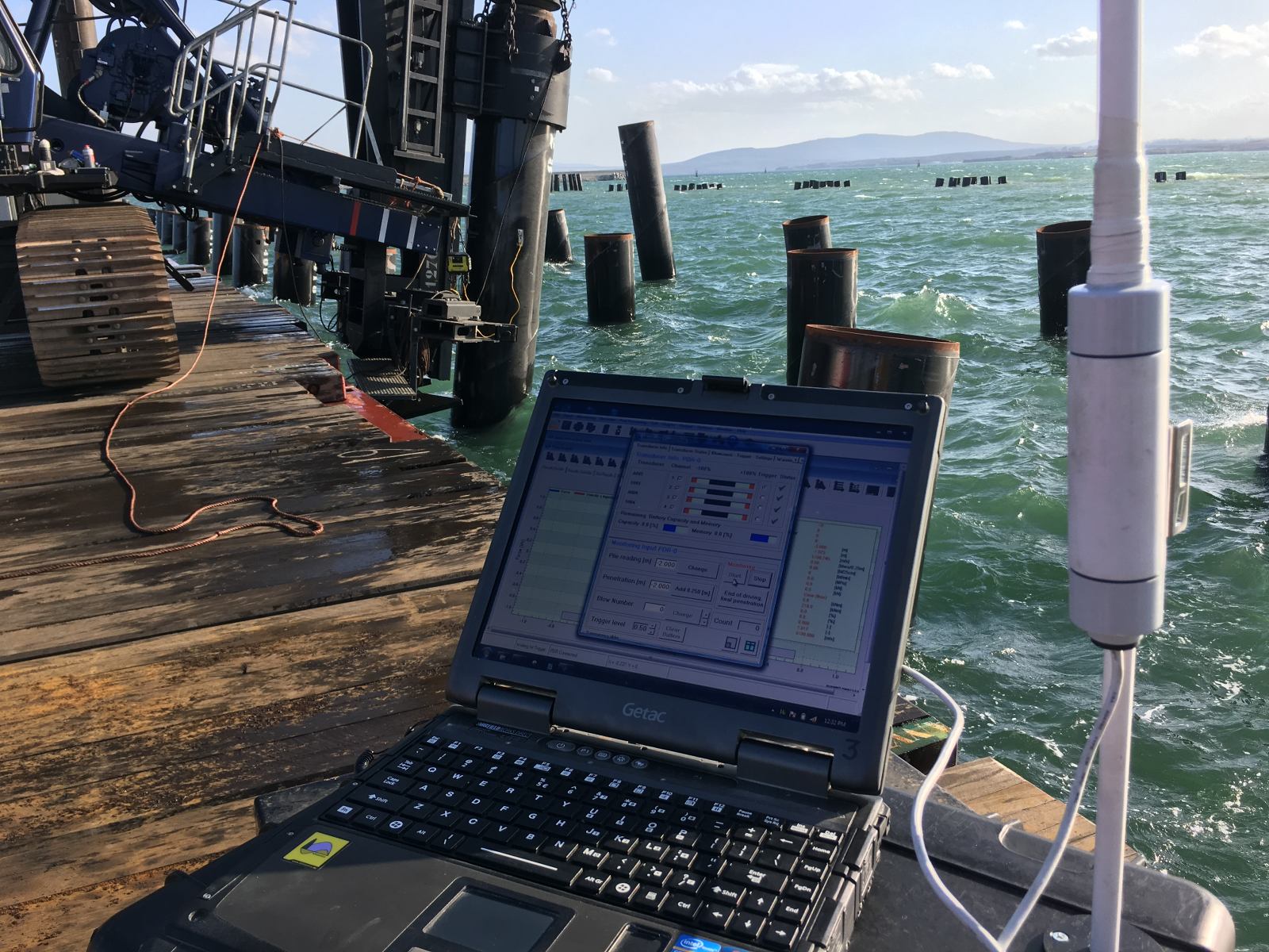
Real-time stress monitoring during pile installation uses strain gauges and accelerometers attached to the pile near the head to measure force and velocity at every blow. These measurements are processed using stress wave theory to calculate the actual compression and tension stresses the pile experiences, the energy transferred from the hammer, and the soil resistance at the time of driving. This data is then compared directly against the predictions from the drivability study.
The monitoring process serves two functions simultaneously. First, it confirms whether the hammer is performing as assumed in the analysis and whether the soil resistance matches the predicted SRD profile. Second, it provides a real-time safety check, alerting the installation team if measured stresses approach or exceed allowable limits before pile damage occurs.
When measured stresses diverge significantly from predictions, the installation team can respond immediately: adjusting hammer stroke, changing the driving sequence, or stopping to reassess the soil model. This feedback loop between prediction and measurement is what makes drivability analysis a practical installation management tool rather than a purely theoretical exercise.
Signal matching, in which the measured force and velocity records are used to back-calculate soil resistance and refine the soil model, further improves the accuracy of predictions for subsequent piles on the same project. This is particularly valuable on large offshore projects where dozens of piles are installed in similar ground conditions, because early monitoring results can be used to update the drivability model and reduce uncertainty for the remaining installation program.
How We Support Drivability Predictions and Stress Analysis
At Allnamics, we carry out complete drivability studies for impact and vibratory pile installation, combining advanced stress wave modeling with decades of experience in foundation engineering. Our approach covers the full scope of what a reliable prediction requires:
- AllWave-PDP for impact driving: We use AllWave-PDP to simulate the hammer-pile-soil system blow by blow, producing blow count versus penetration curves, maximum compression and tension stresses, energy transfer, and refusal risk assessments across the full installation depth.
- AllWave-VDP for vibratory driving: For vibratory installation, our AllWave-VDP software models soil fatigue as a function of local loading history rather than applying a uniform degradation factor, giving a more physically realistic picture of penetration resistance and pile stresses.
- CPT-based soil modeling: We build SRD profiles directly from CPT data using established empirical models, including friction fatigue relationships calibrated against offshore and onshore driving records.
- Hammer and cushion optimization: We evaluate multiple hammer configurations and cushion properties to identify the combination that achieves target penetration while keeping compression and tension stresses within allowable limits for your pile material.
- Real-time installation monitoring: We provide on-site dynamic monitoring during installation, comparing measured stresses and energy transfer against predictions and updating the soil model as driving progresses.
- Independent technical review: For projects where an independent assessment is required, we review existing drivability studies and provide a documented technical opinion on the reliability of the predictions and the adequacy of the proposed installation approach.
If your project involves driven piles and you need a reliable prediction of compression stresses, installation performance, or refusal risk, contact our team to discuss how we can support your project from design through installation.