What is the soil fatigue model in AllWave-VDP?
The soil fatigue model in AllWave-VDP calculates how soil resistance along a pile shaft decreases progressively as the pile accumulates vibration cycles during vibratory driving. It does this by tracking the local loading history at each point along the shaft and applying a depth-dependent reduction to shaft friction, rather than assuming a single uniform reduction factor for the entire pile. The sections below unpack how this model works, which soils it affects most, and when your team should apply it in practice.
How does soil resistance change during vibratory pile driving?
During vibratory pile driving, soil resistance along the pile shaft decreases progressively as the number of vibration cycles increases. This reduction, commonly called friction fatigue, occurs because repeated cyclic loading breaks down the structure of the soil at the pile-soil interface, reducing the effective friction that the soil can mobilize against the pile surface.
The mechanism differs fundamentally from impact driving. A vibratory hammer operating at 23 Hz can generate roughly 10,000 cycles in approximately seven minutes. During that time, the soil at the top of the pile shaft has experienced the full loading history, while the soil immediately around the current pile tip has only been subjected to a fraction of those cycles. This means resistance is not uniform along the shaft at any given moment during installation.
A simplified approach to capturing this behavior is the Beta Factor, originally proposed by Jonker, which describes the ratio between residual and initial soil strength. While useful as a first approximation, a constant Beta applied uniformly across the entire pile length does not reflect physical reality. The soil at different depths has experienced different numbers of cycles, and its residual strength should reflect that difference. A physically realistic model must therefore treat fatigue as a function of local loading history rather than applying a single global reduction.
What does the soil fatigue model in AllWave-VDP calculate?
The soil fatigue model in AllWave-VDP calculates the depth-dependent reduction in shaft friction as a function of the cumulative number of loading cycles experienced at each point along the pile. Instead of applying a single Beta Factor uniformly, the model tracks how many cycles each soil layer has undergone and reduces local resistance accordingly, producing a realistic distribution of residual shaft friction during vibratory driving.
AllWave-VDP is built on one-dimensional stress-wave analysis using the Method of Characteristics (MoC), the same theoretical foundation that underpins AllWave-PDP for impact driving. The AllWave software package models the coupled interaction between the vibratory hammer, the pile, and the surrounding soil at each time step. Within this framework, the soil fatigue model introduces a cycle counter for each soil element along the shaft. As the pile penetrates, upper elements accumulate more cycles than lower elements, and the model applies progressively greater friction reduction to those upper layers.
The outputs of the soil fatigue model include:
- Residual shaft friction as a function of depth at any point during installation
- Total soil resistance to driving (SRD) as penetration progresses
- Predicted penetration rate and the risk of early refusal
- Pile displacement and velocity profiles over time
This approach separates the static soil resistance, which contributes to long-term pile capacity, from the dynamic soil resistance, which arises from velocity-dependent damping during driving and does not directly reflect static bearing capacity. Keeping these components distinct is important for interpreting both drivability and post-installation capacity.
Which soil types are most affected by fatigue during vibro-driving?
Cohesive soils, particularly soft to medium clays, are most strongly affected by friction fatigue during vibratory driving. In these soils, cyclic loading disrupts the soil structure at the pile-soil interface, causing significant reductions in effective shaft friction over relatively few cycles. Loose to medium-density sands also show notable fatigue effects, especially when vibration causes local densification or pore pressure changes around the pile.
Dense sands and gravels tend to show less pronounced fatigue in terms of friction reduction, but they present a different challenge: the soil may densify rapidly around the pile, increasing toe resistance and potentially causing early refusal before the pile reaches target penetration. Chalk, which behaves in a brittle and structure-sensitive way, can also experience significant strength degradation under cyclic loading, as documented in research on pile drivability in low-to-medium density chalk.
The practical implication is that the soil fatigue model is not equally relevant for every project. In stiff clays or dense granular profiles, the model still applies, but the magnitude of fatigue-driven resistance reduction will differ substantially from what you would see in soft clay or loose sand. Selecting the correct fatigue parameters for the specific soil type encountered on your project is therefore a key step in producing a reliable vibratory driving prediction.
How does the soil fatigue model improve drivability predictions?
The soil fatigue model improves drivability predictions by replacing a uniform resistance assumption with a physically realistic, depth-varying resistance profile. This allows AllWave-VDP to predict not just whether a pile can reach target penetration, but also where along the installation process resistance changes are likely to occur, including the risk of early refusal at intermediate depths.
Without a fatigue model, a vibratory driving prediction based on a constant Beta Factor may underestimate resistance near the pile tip and overestimate it near the top of the shaft simultaneously. This can lead to misleading conclusions about hammer selection, required power, and achievable penetration rates. The depth-dependent approach corrects this by reflecting the actual state of the soil at each moment during installation.
The improvement is most visible in complex soil profiles where resistance varies significantly with depth. In a profile with alternating soft and stiff layers, the fatigue model captures how the pile moves through each layer differently, accumulating cycles at different rates in each zone. This produces a more accurate blow-by-blow picture of the installation process.
Drivability predictions also become more useful when they are validated against field measurements. The recommended workflow connects prediction, installation monitoring, and back-analysis in a continuous learning loop:
- Build an initial soil model from ground investigation data, including CPT results
- Run a vibratory driving prediction using AllWave-VDP with the fatigue model active
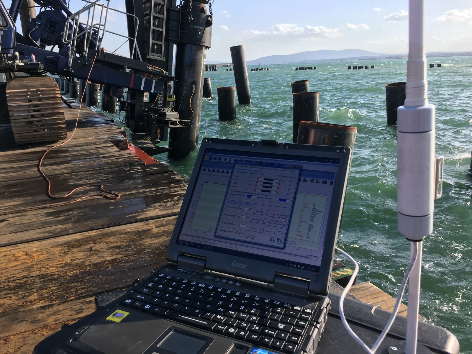
- Monitor the actual installation and record penetration rate, force, velocity, and acceleration
- Perform signal matching and back-analysis to refine the soil model
- Compare predicted and measured results, and update the model for future predictions
This iterative process turns each installation into a calibration exercise, progressively improving the reliability of future predictions on similar projects.
What input parameters does the soil fatigue model require?
The soil fatigue model in AllWave-VDP requires input parameters that describe both the initial soil resistance profile and the rate at which resistance degrades under cyclic loading. The primary inputs are the initial shaft friction distribution, the fatigue degradation function or Beta Factor per soil layer, and the number of cycles required to reach residual resistance in each layer.
In practice, these parameters are derived from several sources:
- CPT data: Cone penetration test results provide the basis for estimating initial unit shaft friction along the pile. CPT-based soil modeling is a standard starting point for both AllWave-PDP and AllWave-VDP analyses.
- Soil classification: The soil type at each depth determines which fatigue degradation function applies. Clay, sand, chalk, and mixed profiles each require different parameter sets.
- Pile geometry: Diameter, wall thickness, material, and total length affect how stress waves propagate and how the pile interacts with the surrounding soil.
- Hammer characteristics: Frequency, eccentric moment, and operational settings of the vibratory hammer determine the number of cycles generated per unit time and the energy input to the system.
- Beta Factor or equivalent degradation parameter: This defines the ratio of residual to initial shaft friction for each soil layer, ideally calibrated against back-analysis data from previous installations in comparable conditions.
Where project-specific calibration data is not yet available, published correlations and experience databases provide a starting point. As monitoring data from the actual installation becomes available, these parameters can be updated through signal matching and back-analysis, improving the accuracy of the model for the remainder of the project.
When should engineers apply the soil fatigue model in a project?
Engineers should apply the soil fatigue model whenever vibratory driving is planned and the soil profile includes layers where cyclic resistance degradation is expected to influence penetration behavior. This applies particularly to projects in soft to medium clays, loose to medium sands, or mixed profiles where early refusal is a realistic risk.
For straightforward profiles in dense granular soils where fatigue effects are minor, a simplified approach with a constant Beta Factor may be sufficient for a preliminary assessment. However, as soon as the project involves large-diameter piles, long penetration depths, sensitive soil conditions, or tight installation tolerances, the depth-dependent fatigue model adds meaningful value.
Specific situations where applying the full fatigue model is strongly recommended include:
- Offshore monopile or jacket installation where early refusal would have significant cost and schedule consequences
- Projects where the vibratory hammer will be used to reach a deep target penetration through variable soil layers
- Sites where previous installations have shown unexpected resistance build-up or refusal at intermediate depths
- Projects combining vibratory driving with subsequent impact driving, where the residual resistance state after vibro-driving affects the impact phase
- Any project where post-installation capacity assessment depends on understanding how driving has altered the soil state around the pile
Applying the fatigue model early in the design phase also supports hammer selection. If the model shows that a particular hammer configuration will not generate sufficient energy to overcome fatigue-reduced resistance at depth, your team can evaluate alternatives before mobilization rather than discovering the problem on site.
How We Support Vibratory Driving Predictions with AllWave-VDP
We develop and apply AllWave-VDP as part of our broader drivability engineering practice, combining the soil fatigue model with CPT-based soil modeling, installation monitoring, and back-analysis to deliver predictions that are both technically rigorous and practically useful. Our approach covers the full workflow from initial prediction through to post-installation validation.
When your team works with us on a vibratory driving prediction, we provide:
- CPT-based soil model development tailored to the specific pile geometry and hammer configuration on your project
- AllWave-VDP analysis with the depth-dependent soil fatigue model, producing penetration rate predictions, resistance profiles, and early refusal risk assessments
- Hammer selection support based on predicted resistance and fatigue behavior throughout the installation depth
- Installation monitoring during vibratory driving to capture real-time force, velocity, and penetration data
- Signal matching and back-analysis to refine the soil model and validate or update the original prediction
- Combined vibratory and impact driving analysis for projects where both methods are used in sequence
Our experience with offshore and onshore pile installations, including large-diameter monopiles and jacket foundations, means we can draw on a broad database of calibrated soil models and fatigue parameters when project-specific data is limited at the start of a project.
If you are planning a project that involves vibratory pile driving and want to understand the drivability risks before mobilization, contact our team to discuss how we can support your prediction and monitoring program.