

What is friction fatigue during pile driving?
Friction fatigue is the progressive reduction in shaft friction along a pile’s upper sections as the pile is driven deeper into the ground. Each time the pile advances, soil that was once close to the pile tip moves further up the shaft, experiencing more loading cycles and losing contact stress, which reduces the unit skin friction it can mobilize. This phenomenon affects both drivability predictions and the long-term bearing capacity of driven piles, and it behaves differently depending on soil type, pile geometry, and installation method. The sections below address the most common questions engineers ask about friction fatigue in practice.
How does shaft friction degrade as a pile is driven deeper?
Shaft friction degrades as a pile is driven deeper because soil elements that were once near the pile tip gradually move up the shaft, accumulating loading cycles and losing lateral effective stress. The unit skin friction at any point along the shaft is not fixed: it decreases as the distance between that soil element and the current pile tip increases. This distance-dependent reduction is the defining characteristic of friction fatigue.
When a pile is first driven past a soil layer, that layer experiences high radial stress and mobilizes strong frictional resistance. As the pile continues to penetrate, the same layer is no longer near the advancing tip. The stress bulb moves downward, and the soil around the upper shaft undergoes stress relaxation. In granular soils, arching effects and grain rearrangement reduce the horizontal effective stress acting on the pile surface, directly lowering the available friction. In cohesive soils, repeated shearing remolds the clay structure around the pile, progressively reducing the undrained shear strength that governs skin friction.
The result is that the friction profile along a driven pile is not uniform. The highest unit skin friction occurs near the pile tip, while the upper sections of the shaft carry significantly less friction per unit length than they would if the pile had been loaded statically from the surface without driving. This non-uniform distribution has direct consequences for both installation resistance and the pile’s capacity after driving is complete.
What causes friction fatigue in different soil types?
Friction fatigue in sands is driven primarily by stress relaxation and grain rearrangement, while in clays it is caused by remolding and cyclic degradation of the soil structure. The underlying mechanisms differ, but the outcome is the same: unit shaft friction decreases with increasing distance from the pile tip.
Friction fatigue in granular soils
In sands and gravels, the lateral effective stress acting on the pile shaft is the main driver of skin friction. As the pile advances, the soil grains around the upper shaft rearrange and the stress arch that forms around the pile tip migrates downward. This reduces the radial stress on the shaft above the tip, and with it the frictional resistance. Vibratory driving amplifies this effect considerably: a vibratory hammer operating at 23 Hz can produce roughly 10,000 loading cycles in approximately seven minutes, and soil near the top of the shaft experiences the full history of those cycles while soil near the current pile tip has experienced far fewer. This position-dependent cycle count is why a single uniform reduction factor for the entire shaft, such as the classical Beta Factor approach originally proposed by Jonker, is a simplification that does not reflect the physical reality of how friction degrades along the pile.
Friction fatigue in cohesive soils
In clays, friction fatigue is governed by cyclic remolding. Each driving blow or vibration cycle shears the clay around the pile interface, progressively breaking down the soil structure. The undrained shear strength of the remolded clay is lower than that of the intact material, so the unit skin friction drops. Research using the Alm and Hamre model shows that in normally consolidated clay, residual friction is typically reached after approximately 30 meters of further pile penetration past a given soil element, while in heavily overconsolidated clay with an OCR above 16, the same residual condition can be reached after as little as 10 meters. This means overconsolidated clays degrade faster in relative terms, even though their absolute friction values may remain higher.
How does friction fatigue affect final pile bearing capacity?
Friction fatigue reduces the unit shaft friction that a driven pile can mobilize under static loading after installation. Because the upper sections of the shaft have experienced the most loading cycles during driving, they carry less friction per unit length than they would in a pile installed without cyclic degradation. The total bearing capacity of the pile is therefore lower than a simple static analysis based on intact soil properties would suggest.
This distinction between initial shaft friction and residual shaft friction is central to accurate pile design. A capacity calculation that ignores friction fatigue will overestimate the contribution of the upper shaft, potentially leading to unconservative designs. The degree of overestimation depends on pile length, soil type, and installation method. Long piles in sand driven with many blows are particularly susceptible, because the upper shaft has experienced a large number of stress cycles by the time the pile reaches its final depth.
It is worth noting that some capacity recovery occurs after driving stops. In clays, pore pressure dissipation and soil reconsolidation around the pile shaft allow friction to rebuild over time, a process known as pile setup. In sands, setup is generally less pronounced but still present. Driveability predictions and capacity assessments should therefore distinguish between the resistance during driving, the capacity immediately after driving, and the long-term static capacity after setup.
What is the h/D ratio and why does it matter for friction fatigue?
The h/D ratio describes the distance between a given soil element and the current pile tip (h) normalized by the pile diameter (D). It is the standard way to quantify how far a soil element has traveled up the shaft relative to the pile size, and it directly governs the degree of friction fatigue that element has experienced. A higher h/D value means the soil element is further from the tip and has undergone more stress reduction.
The h/D ratio matters because it provides a physically meaningful, geometry-independent measure of friction degradation. A soil element at h/D = 5 has experienced a moderate level of stress relaxation; the same element at h/D = 40 has experienced near-complete degradation toward its residual friction value. Using h/D allows engineers to apply friction fatigue models consistently across different pile diameters and lengths without recalibrating the degradation curve for each project.
In practice, design methods such as the Alm and Hamre model use h/D as the primary variable in exponential degradation functions that transition from initial to residual shaft friction. For open-ended tubular piles, common in offshore applications, the effective h/D at any point along the shaft changes continuously as the pile is driven, which is why a full driveability simulation that tracks this ratio at each penetration increment produces more reliable results than a simplified hand calculation.
How do engineers account for friction fatigue in pile design?
Engineers account for friction fatigue by applying degradation models that reduce unit shaft friction as a function of the h/D ratio, soil type, and number of loading cycles. These models replace the assumption of uniform skin friction along the shaft with a depth-dependent profile that reflects the actual stress history each soil element has experienced during pile installation.
The most widely used approaches in practice include:
- CPT-based methods: Cone Penetration Test data provides a continuous profile of soil resistance that can be translated into initial shaft friction values. Degradation functions are then applied to account for friction fatigue, producing a realistic residual friction profile for driveability and capacity calculations.
- The Beta Factor approach: A simplified method that applies a single reduction factor to the initial shaft friction across the full shaft length. This is computationally straightforward but physically imprecise, because it does not capture the fact that soil near the top of the shaft has experienced far more cycles than soil near the tip.
- Position-dependent fatigue models: More advanced models treat friction fatigue as a function of local loading history at each point along the shaft. This approach recognizes that soil near the current pile tip has experienced few cycles while soil at the top of the shaft may have experienced thousands, and it distributes residual friction accordingly.
- Driveability simulation software: Programs that simulate the full installation process blow by blow, or cycle by cycle for vibratory driving, can track the evolving friction profile and predict both installation resistance and post-driving capacity with greater accuracy.
A reliable design also quantifies uncertainty. The quality of any friction fatigue prediction is bounded by the quality of the soil investigation data and by how systematically previous predictions have been compared against measured installation records.
Can friction fatigue be reduced during pile installation?
Friction fatigue cannot be eliminated, but installation choices can influence how quickly and severely it develops. The choice of hammer type, driving energy, and pile geometry all affect the number of loading cycles the soil experiences and the rate at which friction degrades along the shaft.
For impact-driven piles, using a heavier hammer with fewer blows per meter of penetration reduces the total number of stress cycles the soil experiences compared to a lighter hammer that requires many more blows to achieve the same penetration. Fewer cycles mean less cumulative degradation of the soil structure around the upper shaft. However, this trade-off must be balanced against pile stress limits: a heavier hammer increases compressive and tensile stresses in the pile, which can cause structural damage if not carefully managed.
For vibratory driving, the relationship between frequency, eccentric moment, and displacement amplitude is particularly relevant. A hammer with a larger eccentric moment and lower operating frequency produces a greater displacement amplitude per cycle. In cohesive soils, sufficient displacement amplitude is needed to push the soil past its elastic range and generate permanent penetration. Choosing a hammer configuration that achieves the required penetration with fewer total cycles can limit the extent of friction fatigue, though the optimal configuration depends on soil conditions and pile geometry.
Pile geometry also plays a role. Open-ended tubular piles allow soil to enter the pile interior, which can reduce the effective base resistance and alter the distribution of shaft friction. The interaction between internal shaft friction, external shaft friction, and plug formation changes how friction fatigue develops along both the inner and outer surfaces of the pile, a factor that becomes particularly important when interpreting dynamic load test results for open-ended piles.
How Allnamics Helps with Friction Fatigue Analysis and Driveability Predictions
We work with clients across offshore wind, oil and gas, marine infrastructure, and civil construction to build friction fatigue into driveability predictions from the start, not as an afterthought. Our approach combines advanced soil modelling, CPT-based interpretation, and simulation software to give your team a realistic picture of installation resistance and post-driving capacity before a single pile is driven.
Here is what we offer in this area:
- Driveability studies using AllWave-PDP and AllWave-VDP: Our AllWave software package simulates the full hammer-pile-soil interaction for both impact and vibratory driving, tracking friction fatigue as a function of local loading history at each penetration increment rather than applying a single uniform reduction factor.
- CPT-based soil modelling: We translate Cone Penetration Test data into position-dependent friction profiles that reflect initial and residual shaft friction, giving your design a physically grounded basis for capacity and drivability predictions.
- Uncertainty quantification: We present results across a range of soil resistance scenarios, lower bound, best estimate, and upper bound, so your team can assess refusal risk, early set-up, and capacity variability before committing to an installation strategy.
- Pile stress verification: Alongside friction fatigue modelling, we check compressive and tensile stresses throughout the installation process to confirm that hammer selection does not compromise pile integrity while achieving the target penetration depth.
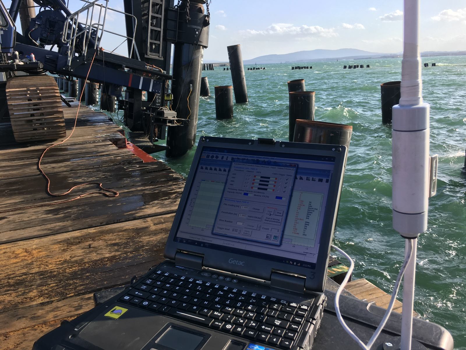
- Installation monitoring and back-analysis: We support predictions with field measurements during driving, allowing real-time comparison between predicted and measured behaviour and rapid adjustment if conditions differ from the soil model.
If your project involves driven piles in challenging soil conditions and you want friction fatigue properly accounted for in your design, contact us to discuss how we can support your driveability study.