

How do stress waves travel through a pile during impact driving?
When a hammer strikes a pile, it generates a longitudinal stress wave that travels down through the pile material at high speed: it does not load the entire pile simultaneously. This wave propagates from the point of impact toward the pile toe, interacting with the surrounding soil and any changes in the pile’s cross-section or material along the way. Understanding how these stress waves behave is the foundation of modern pile driving analysis, drivability prediction, and pile integrity assessment. The sections below answer the most common questions engineers ask about stress wave mechanics in driven piles.
What happens inside a pile the moment a hammer strikes it?
The instant a hammer contacts the pile head, it does not compress the entire pile at once. Instead, the impact generates a compressive stress wave that travels downward through the pile as a longitudinal wave. Different parts of the pile experience different stresses, velocities, and displacements at the same moment: the pile behaves as a dynamic, distributed system rather than a rigid body.
This is a point that classical rigid-body mechanics cannot capture. The hammer delivers an impact force-time history to the pile head, and the shape and magnitude of that pulse depend on the hammer type, the cushion material between hammer and pile, and the stiffness of the pile-soil system. A cushion with lower stiffness spreads the pulse over a longer duration and reduces peak stress, while a stiffer cushion transmits a sharper, higher-amplitude wave. This means the cushion is an active part of the dynamic system, not a neutral buffer.
Because the load travels as a wave, different cross-sections of the pile can be in compression and tension simultaneously during a single hammer blow. For concrete piles in particular, this has direct consequences: tension zones can cause cracking if the tensile stress exceeds the material’s capacity. Monitoring this behavior during installation is therefore not only about tracking penetration: it is about protecting pile integrity throughout the driving process.
How fast do stress waves travel through steel and concrete piles?
The wave propagation speed in a pile depends on the material’s elastic modulus and mass density. For steel piles, the wave speed is approximately 5,100 meters per second. For concrete piles, it typically falls between 3,500 and 4,000 meters per second, depending on concrete mix and condition. This speed is the foundation of all stress wave-based pile analysis methods.
The classical one-dimensional wave equation expresses this relationship as:
c = √(E / ρ)
where E is the elastic modulus and ρ is the mass density of the pile material. A central quantity linked to this is the mechanical impedance of the pile, defined as the product of the cross-sectional area, the wave speed, and the material density. Impedance connects the force in the pile to the particle velocity at any given cross-section: if you know one, you can calculate the other.
This relationship has a practical implication: any change in impedance along the pile (a change in cross-section, a material transition, a splice, or a defect) will cause part of the stress wave to reflect back toward the pile head and part to transmit onward. The timing and amplitude of those reflections carry information about where and what the change is.
What causes stress wave reflections at the pile toe and along the shaft?
Stress wave reflections occur wherever the pile’s mechanical impedance changes or where the pile interacts with a boundary condition. At the pile toe, the wave encounters the soil beneath the tip. Along the shaft, friction between the pile and surrounding soil continuously modifies the wave as it travels downward.
Reflections at the pile toe
When the downward-traveling compressive wave reaches the pile toe, it interacts with the soil resistance at that point. If the toe is effectively fixed, meaning the soil provides strong resistance, the wave reflects back as a compressive wave. If the toe is relatively free, the reflection returns as a tensile wave. This reflected tensile wave traveling upward can, under certain conditions, cause tension in the upper portions of the pile, a known risk for concrete piles that are not designed to handle significant tensile loads.
Reflections along the shaft
Along the pile shaft, soil friction acts as a distributed resistance that partially absorbs and reflects the stress wave at every depth increment. Discontinuities in the pile itself, such as changes in cross-section, cracks, or material joints, also generate reflections. The amplitude and polarity of each reflection depend on whether impedance increases or decreases at that point. An increase in impedance produces a compressive reflection; a decrease produces a tensile one. Interpreting the pattern of reflections is what allows engineers to locate anomalies and assess soil resistance distribution.
How do engineers measure and interpret stress waves during driving?
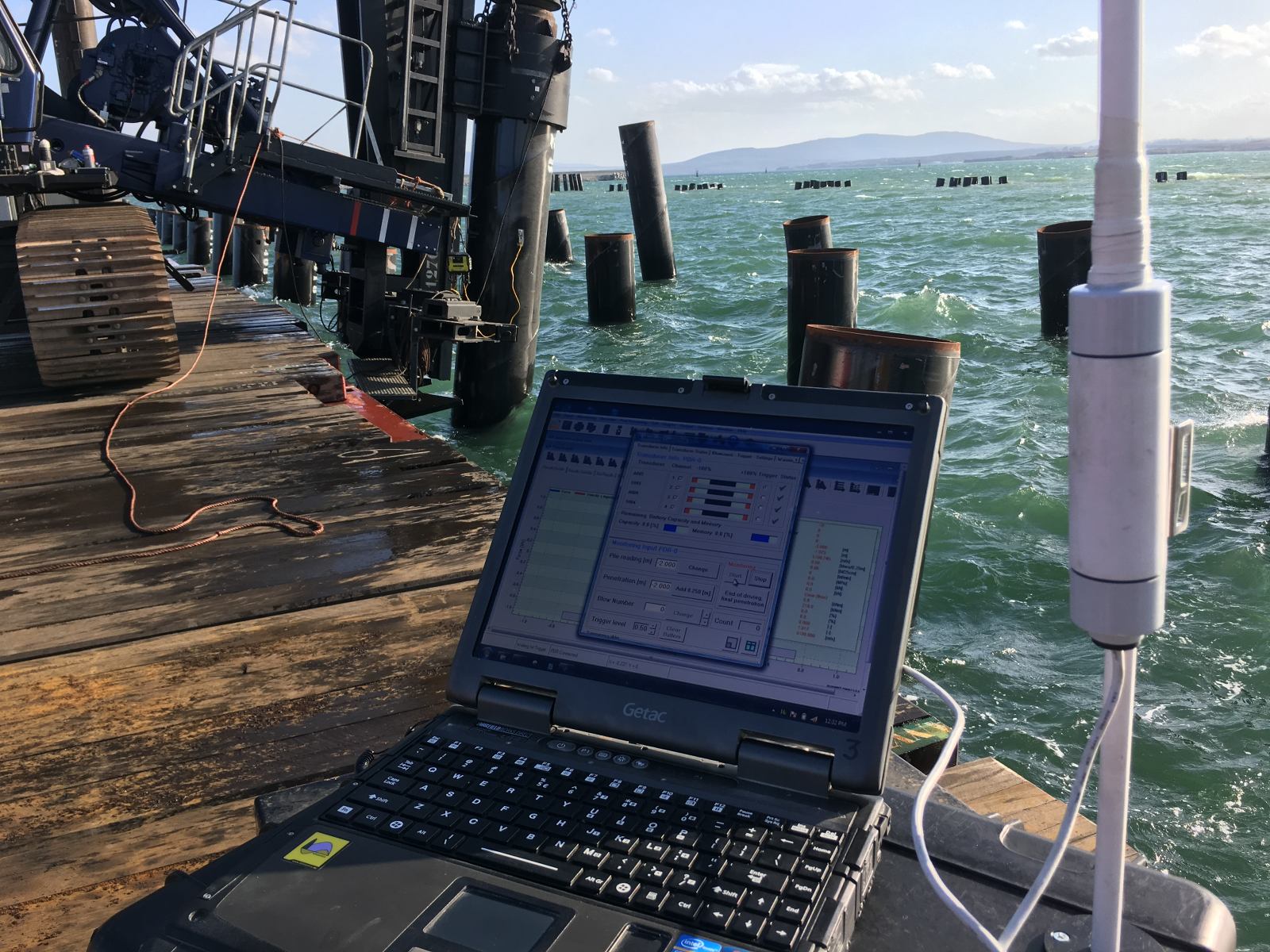
Engineers measure stress waves during pile driving by attaching strain gauges and accelerometers to the pile near the head. Strain gauges record the force history at that cross-section, while accelerometers capture particle velocity. Together, these measurements give a complete picture of the stress wave passing through the instrumented location in real time.
This approach forms the basis of Dynamic Load Testing (DLT) and Pile Driving Analysis (PDA). The raw signals, force and velocity as functions of time, are processed using wave equation analysis. By applying the Method of Characteristics (MoC), engineers can separate the upward- and downward-traveling wave components and use them to back-calculate soil resistance, energy transfer, and pile integrity.
Signal matching is a further step in this process. Engineers adjust a numerical model of the hammer-pile-soil system until its simulated signals match the measured ones. The resulting model parameters, soil resistance distribution, damping, and stiffness, represent the best estimate of actual conditions during driving. This technique connects field measurements directly to the theoretical framework of one-dimensional stress wave propagation.
What can stress wave data reveal about pile integrity and soil resistance?
Stress wave data can reveal both the structural condition of the pile and the distribution of soil resistance along its length. Reflections arriving earlier than expected from the pile toe indicate an anomaly, a crack, a void, or a cross-section reduction, at the depth corresponding to that travel time. Reflections from the toe itself indicate the level of end-bearing resistance mobilized during the blow.
From a soil resistance perspective, the analysis can distinguish between shaft friction and toe resistance, estimate the total soil resistance to driving (SRD), and track how resistance changes with depth as the pile penetrates further. This information feeds directly into drivability assessments: if resistance builds faster than predicted, the blow count increases and refusal risk rises.
For pile integrity, the data supports decisions about whether a pile has sustained damage during driving. Tension cracks in concrete piles, for example, alter the local impedance and produce characteristic reflections. Detecting these changes during installation, rather than after, allows your team to respond before the damage becomes irreversible. Sonic Integrity Testing (SIT) applies the same wave propagation principles to assess existing piles where no driving records are available.
How does stress wave behavior differ between driven and vibratory pile installation?
In impact driving, a hammer generates discrete stress wave pulses, one per blow, that travel through the pile and return as reflections. In vibratory driving, there are no individual impact pulses. Instead, a vibratory hammer imposes continuous cyclic motion on the pile, generating oscillating displacements, velocities, and accelerations rather than propagating stress waves in the classical sense.
This physical difference has significant consequences for analysis. The soil reaction model used for impact driving, where static resistance and dynamic damping are combined in a straightforward way, does not translate directly to vibratory conditions. For vibratory driving, the soil reaction must be expressed as a function of displacement, velocity, and acceleration simultaneously, and the relationship between these quantities is more complex than simple linear constants can capture.
Another important difference is how soil resistance evolves during installation. In vibratory driving, the cyclic motion disturbs the soil around the pile, temporarily reducing shear resistance. In granular soils, this reduction can be very large, allowing the pile to advance primarily under the combined static weight of the hammer and pile. In cohesive soils, more residual strength remains, and penetration requires sufficient displacement amplitude to generate plastic behavior in the soil. This is why vibratory driving tends to be more effective in sandy ground than in stiff clay.
Soil fatigue is also a more prominent factor in vibratory installation. The soil near the top of the pile shaft may experience thousands of loading cycles before the pile reaches its final depth, while soil near the current pile tip has experienced far fewer. A realistic analysis must account for this variation in loading history along the shaft: a uniform residual strength assumption is physically inaccurate for vibratory conditions.
How Allnamics Supports Stress Wave Analysis and Drivability Prediction
We have built our drivability and stress wave analysis capabilities on decades of direct involvement in developing the methods that underpin the field today. Our founders contributed to the development of Sonic Integrity Testing, Dynamic Load Testing, and the wave equation solutions that are now standard practice in foundation engineering. That background shapes how we approach every project.
Our AllWave Software Package puts this expertise into practice. It covers both impact and vibratory pile installation through two dedicated programs:
- AllWave-PDP for impact drivability prediction, simulating hammer, pile, and soil resistance to predict blow count, penetration, compressive and tensile stresses, energy transfer, and refusal risk across the full installation depth
- AllWave-VDP for vibratory driving prediction, applying the Method of Characteristics with soil reaction models specifically developed for cyclic loading conditions, including soil fatigue as a function of local loading history
Beyond software, we provide the following services directly relevant to stress wave behavior and pile performance:
- Dynamic Load Testing (DLT) with signal matching to back-calculate soil resistance and verify pile integrity during or after driving
- Pile Driving Analysis (PDA) for real-time monitoring of stress waves, energy transfer, and pile condition during installation
- Sonic Integrity Testing (SIT) for assessing existing piles using stress wave reflections
- Drivability studies that combine CPT-based soil modeling with hammer library data to predict installation performance before a single pile is driven
- Hammer selection and cushion optimization to balance penetration performance against pile stress limits
Whether your project involves impact-driven steel piles for an offshore wind foundation, concrete piles for a building structure, or vibratory installation in granular soils, we can help you predict, monitor, and verify performance at every stage. Contact us to discuss your project requirements with our team.