

During pile driving, maximum tension stresses are predicted using one-dimensional stress-wave analysis, which simulates how a hammer impact travels through the pile and interacts with the surrounding soil. The analysis calculates the magnitude and location of tensile forces that develop when stress waves reflect back up the pile, particularly at the pile toe or at boundaries where soil resistance changes sharply. Tools such as AllWave-PDP for impact driving and AllWave-VDP for vibratory driving perform these calculations automatically across the full installation depth, giving engineers a complete picture of pile integrity risk before a single blow is struck.
What causes tension stresses to develop in a pile during driving?
Tension stresses develop in a pile during driving when a downward-travelling compressive stress wave reflects back upward as a tensile wave. This reflection occurs primarily at the pile toe when soil resistance there is low relative to the incoming wave energy. The returning tensile wave can exceed the material’s tensile capacity, causing cracking in concrete piles or yielding in steel sections.
The mechanism works as follows: every hammer blow generates a compressive wave that travels down the pile at a speed determined by the pile material and cross-section. When that wave reaches the pile toe, the nature of the reflection depends on the toe resistance. High toe resistance reflects the wave back as compression. Low toe resistance (for example, when the pile tip is still in soft soil) reflects the wave back as tension. The same effect can occur at any point along the shaft where pile impedance changes abruptly, such as at a splice or a section change.
A secondary source of tension is the interaction between shaft friction and the propagating wave. When a pile passes through a hard layer into a softer one, the sudden reduction in shaft resistance can also generate upward-travelling tensile components. In long piles, multiple reflections can overlap and amplify the tensile stress at specific depths, making the prediction of peak values more complex than a simple single-reflection model would suggest.
How does wave equation analysis predict maximum tension stresses?
Wave equation analysis predicts maximum tension stresses by modelling the full coupled system of hammer, pile, and soil for every blow at every penetration depth. The method calculates how stress waves propagate, reflect, and interact with soil resistance along the shaft and at the toe, producing time-history outputs of force, velocity, and stress at each node along the pile.
The foundation of this approach is the Method of Characteristics (MoC), which treats the pile as a continuous medium rather than a rigid body. At each time step, the model tracks the upward and downward travelling wave components separately. When the downward compressive wave reaches a boundary (the pile toe, a section change, or a zone of contrasting soil resistance), the model calculates the reflected wave amplitude and sign. If the reflected component is tensile and large enough, it registers as a peak tension stress at that location and time.
A complete driveability analysis using this method does not produce a single tension value. Instead, it generates tension stress profiles as a function of penetration depth, showing where and when the highest tensile demands occur throughout the entire installation sequence. This matters because the critical tension event may not occur at final set: it may occur earlier, when the pile tip is passing through a weak layer beneath a stiff one, or when the blow count is low and the hammer is operating at high energy relative to the available soil resistance.
The quality of the tension stress prediction depends directly on the accuracy of the soil model. Shaft resistance distribution, toe resistance, and dynamic soil damping all influence the reflected wave magnitude. Friction fatigue (the reduction of local shaft resistance as the pile advances and the same soil volume experiences repeated loading cycles) also affects the resistance profile and therefore the tension prediction at each depth increment.
What pile types and soil conditions produce the highest tension stresses?
Concrete piles in soft or variable soil profiles are the most vulnerable to high tension stresses during driving. Concrete has relatively low tensile strength compared to its compressive capacity, so even moderate reflected tensile waves can cause cracking. Steel piles are more tolerant but are not immune, particularly at welds, splices, or sections with reduced wall thickness.
Pile type considerations
Precast concrete piles and prestressed concrete piles are the most tension-sensitive. In prestressed piles, the prestress force offsets some tensile demand, but the net tension limit is still significantly lower than the compressive limit. Reinforced concrete piles without prestress have even less tensile reserve. When tension stresses exceed the tensile strength of the concrete, cracking initiates, and the crack model used in advanced wave equation software, such as the approach developed within the TNOWAVE research lineage, tracks how the changing cross-section impedance at the crack location then modifies subsequent wave propagation.
Open-ended steel tubular piles, common in offshore applications, are generally more forgiving in tension, but high-energy driving through layered profiles can still generate tensile demands that need to be checked against the pile’s yield strength and fatigue criteria.
Soil conditions that amplify tension
Soft toe conditions are the primary driver of high tension. When a pile tip is in very soft clay or loose sand, the toe resistance is low and the reflected tensile wave is large. Layered profiles (for example, a stiff crust over soft material) create conditions where the pile passes through high shaft resistance into a low-resistance zone, generating tensile reflections from the impedance contrast. Hard driving followed by sudden refusal can also produce extreme compression at the toe and corresponding tension higher up the shaft.
What are the allowable tension stress limits for driven piles?
Allowable tension stress limits for driven piles depend on the pile material, the applicable design standard, and whether the pile is prestressed. For precast concrete piles, limits are typically expressed as a fraction of the concrete’s characteristic tensile strength or as a net stress after accounting for prestress. For steel piles, limits are generally set as a fraction of the yield strength.
Common reference frameworks include standards such as EN 12699 (execution of special geotechnical works: displacement piles) and guidance from bodies such as the American Petroleum Institute (API) for offshore steel piles. These standards do not always specify a single universal tension limit; instead, they require that driving stresses remain within the material’s design capacity, which the engineer must verify through a driveability study.
Practical limits used in engineering practice typically follow these broad patterns:
- Prestressed concrete piles: Net tension (after deducting prestress) is often limited to a low positive value or zero, meaning the prestress must be sufficient to keep the pile in net compression under the predicted tensile wave.
- Reinforced concrete piles without prestress: Tension limits are set conservatively, often at a small fraction of the concrete’s tensile strength, because cracking must be avoided to protect reinforcement from corrosion.
- Steel piles: Tension limits are typically set at 90% of the yield strength or lower, with additional checks for fatigue if the pile undergoes many high-stress cycles during installation.
These limits must be checked not just at final penetration but at every depth increment throughout the installation, because the worst tension event may occur at an intermediate depth where soil conditions produce the most unfavourable reflection pattern.
How can tension stresses be reduced during pile installation?
Tension stresses during pile installation can be reduced by adjusting hammer energy, modifying the cushion system, changing the driving sequence, or selecting a hammer better matched to the pile and soil profile. The goal is to reduce the amplitude of the reflected tensile wave without compromising the ability to reach the target penetration depth.
The most direct lever is hammer energy reduction. Driving at a lower stroke or reduced energy per blow lowers the amplitude of the initial compressive wave and therefore the magnitude of any tensile reflection. This is particularly effective in the early stages of driving when the pile tip is still in soft material and toe resistance is low. The trade-off is a higher blow count to achieve the same penetration, which must remain within practical limits.
Cushion selection and thickness also play an important role. A softer or thicker cushion extends the duration of the hammer impact, which reduces the peak stress amplitude of the wave entering the pile. This directly reduces both compressive and tensile peak stresses. However, a very soft cushion also reduces energy transfer efficiency, so the selection requires balancing stress control against driving performance.
For concrete piles specifically, prestressing is the structural measure that provides the most reliable tension protection. By introducing a permanent compressive force into the pile before driving, the net tensile stress under a reflected wave is reduced by the prestress magnitude. This is why prestressed concrete piles are preferred over plain reinforced concrete piles in conditions where tension during driving is a known risk.
At the planning stage, hammer selection is the most powerful tool. A hammer that is too large for the pile and soil combination will generate excessive stresses in both compression and tension. A properly matched hammer, identified through a driveability prediction before mobilisation, avoids this problem entirely. Selecting the right hammer is therefore not only a productivity decision but also a pile integrity decision.
How Allnamics Helps with Tension Stress Prediction During Pile Driving
We combine decades of stress-wave research with our own software tools to give your team accurate, actionable tension stress predictions before installation begins. Our approach covers the full installation sequence, not just the final blow, so you can identify the depth and conditions where tensile risk is highest and take corrective action in advance.
Here is what we provide:
- Driveability studies using AllWave-PDP for impact driving and AllWave-VDP for vibratory driving, producing tension and compression stress profiles as a function of penetration depth; learn more about the AllWave software package
- Soil modelling based on CPT, SPT, and laboratory data, including friction fatigue effects that directly influence the shaft resistance profile and therefore the reflected wave magnitude at each depth
- Hammer selection advice that balances driving performance against pile integrity, identifying the energy range that achieves target penetration without generating unacceptable tension stresses
- Cushion and driving sequence recommendations tailored to your pile type, whether precast concrete, prestressed concrete, or open-ended steel tubular
- Crack modelling for concrete piles, tracking how cracking changes pile impedance and affects subsequent wave propagation, giving you a realistic picture of structural risk, not just a stress number
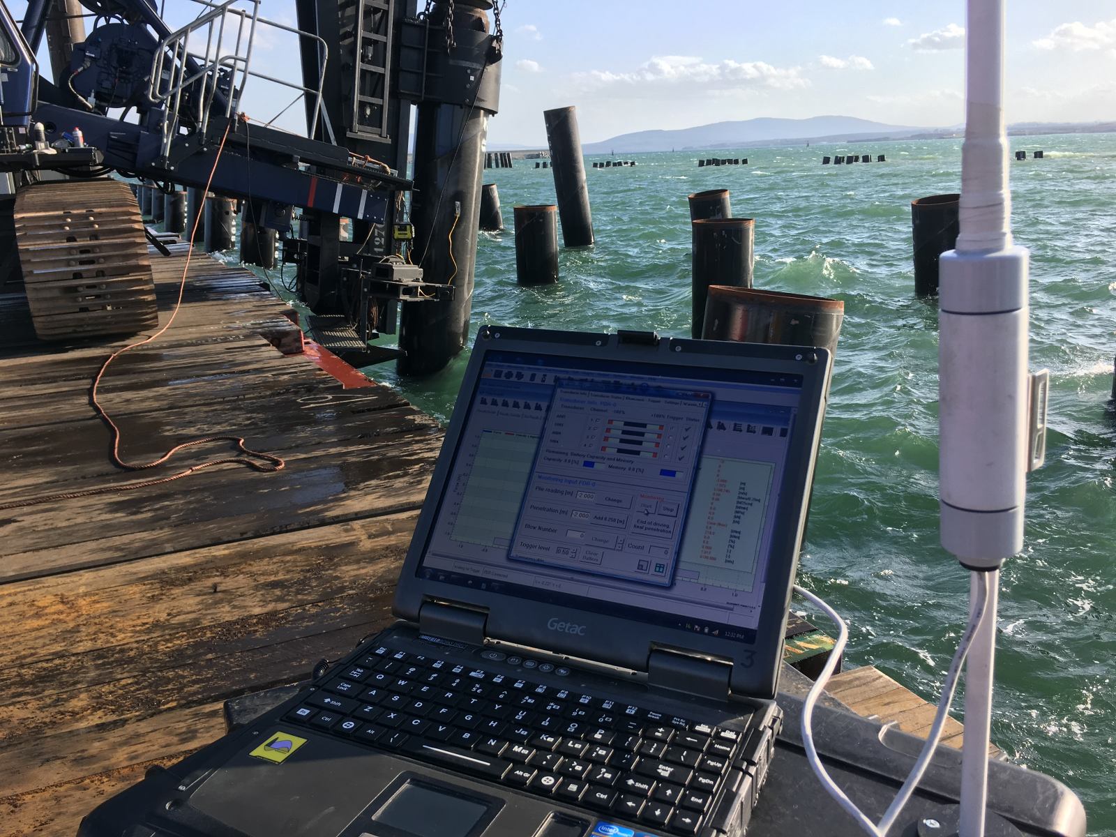
- Installation monitoring and dynamic load testing to verify that actual driving stresses remain within the predicted limits throughout the project
If your project involves driven piles in variable or challenging soil profiles, or if tension cracking in concrete piles is a concern, contact us to discuss how a driveability study can reduce your installation risk.