

When a stress wave reaches the pile toe, it reflects back up through the pile in a form that depends on the boundary conditions at the tip. If the toe meets high soil resistance, the wave reflects as a compressive wave. If the toe is free or meets little resistance, it reflects as a tensile wave. The nature of that reflection carries direct information about soil conditions, pile integrity, and load transfer at depth. The sections below unpack each dimension of this behaviour, from the physics of reflection to what engineers can read from the returning signal.
What determines how a stress wave behaves at the pile toe?
The behaviour of a stress wave at the pile toe is determined by the mechanical impedance contrast between the pile material and the surrounding or underlying medium. Impedance is defined as the product of the pile’s cross-sectional area and elastic modulus divided by the wave velocity: in practical terms, it describes how readily the pile transmits force relative to particle velocity. When the wave reaches the toe, the pile’s impedance meets the impedance of the soil below, and the mismatch between the two governs what happens next.
A pile toe embedded in very stiff soil or rock behaves similarly to a fixed end. The impedance of the surrounding medium is high relative to the pile, so the wave cannot transmit freely and is forced to reflect. At the opposite extreme, a pile toe with no soil contact below it, such as a pile tip hanging in a void or water, behaves like a free end, where impedance drops to near zero and the wave reflects with reversed sign.
Between these two extremes lies the realistic range of soil conditions. Soft clays, loose sands, and partially mobilised soils all produce intermediate reflections. The soil resistance at the toe, including both static resistance and dynamic damping, shapes the amplitude, polarity, and timing of the returning wave. This is why stress wave analysis can extract so much information from a single hammer blow: the reflected signal is a direct physical record of what the pile toe encountered.
What happens when a stress wave reflects back from the pile toe?
When a stress wave reflects from the pile toe, it travels back up the pile as an upward-propagating wave that superimposes on any downward-propagating energy still in the pile. The polarity of the reflected wave, whether it is compressive or tensile, depends on the boundary condition at the toe. A fixed-end condition reflects the wave with the same sign, producing an upward compressive wave. A free-end condition reflects it with opposite sign, producing an upward tensile wave.
This reflected wave arrives at the pile head after a travel time of approximately 2L/c, where L is the pile length and c is the stress wave velocity in the pile material. Engineers use this timing to confirm pile length during integrity testing and to locate anomalies along the shaft. If the reflection arrives earlier than expected, it may indicate a cross-section reduction or a defect at a shallower depth.
The reflected wave also carries energy implications. In a pile with high toe resistance, a large compressive reflection returns to the head, which can temporarily add to the downward force already acting on the pile. In a pile with low toe resistance, the tensile reflection can cause the upper sections of the pile to experience net tension, a condition that is particularly relevant for concrete piles, where tensile capacity is limited. This is one reason why stress wave simulation software models the full time history of wave propagation rather than treating the pile as a rigid body.
How does soil resistance at the pile toe affect the reflected wave?
Soil resistance at the pile toe directly controls the amplitude and character of the reflected wave. High toe resistance produces a strong compressive reflection, while low or absent toe resistance produces a weak or tensile reflection. The relationship is not simply binary: the magnitude of the reflected compressive wave scales with the degree of resistance mobilised during the blow, making the reflection a quantitative indicator of toe load transfer.
Two soil parameters govern this interaction in wave equation analysis: toe quake and toe damping. Toe quake is the elastic deformation required at the pile tip before full static resistance is mobilised. Toe damping represents the velocity-dependent component of soil resistance during dynamic loading. Both parameters influence the shape and timing of the reflected signal in distinct ways.
- Toe quake affects the shape of the signal after the first major return reflection. A higher quake value means the toe resistance builds more gradually, which softens the reflected wave and shifts its peak.
- Toe damping strongly influences the amplitude of the toe reflection. Higher damping produces a larger dynamic resistance component, which can make the toe appear stiffer than its static resistance alone would suggest.
- Mobilisation is a practical constraint: toe resistance is typically mobilised later than shaft resistance during a blow, because the pile tip needs to displace further before full contact is established. If the pile settlement during a blow is insufficient to reach the toe quake, the full static toe resistance will not be mobilised, and the reflected signal will underrepresent it.
This is why signal matching in dynamic load testing requires careful validation of whether the pile settlement was large enough to mobilise toe resistance. A mathematically good numerical fit that assumes full mobilisation when the displacement was insufficient will overestimate the ultimate static capacity at the toe.
How do engineers interpret pile toe reflections during testing?
Engineers interpret pile toe reflections by analysing the force and velocity signals measured at the pile head during a hammer blow. The velocity signal, scaled by pile impedance, is compared to the force signal over time. Deviations between the two signals after the initial impact, particularly around the time 2L/c, reveal what the toe encountered. A sharp compressive return indicates high toe resistance; a weak or tensile return suggests low resistance or a free-end condition.
In Dynamic Load Testing (DLT), this interpretation is formalised through signal matching: engineers build a numerical model of the pile and soil, then adjust soil parameters, including toe quake, toe damping, and static resistance, until the simulated force-velocity response matches the measured signals. The toe reflection is one of the most diagnostic features in this process. A clear, well-timed toe reflection makes it possible to separate toe resistance from shaft resistance near the tip, which would otherwise be difficult to distinguish.
Practical guidelines for reliable interpretation include using multiple consecutive blows rather than a single selected blow, and checking that the resulting soil parameters are physically plausible for the ground conditions at the site. The timing of the toe reflection also provides a cross-check on pile length, which is useful when installation records are incomplete or when testing an existing foundation of unknown depth.
What does a stress wave at the pile toe reveal about pile integrity?
The stress wave at the pile toe reveals whether the pile is continuous, undamaged, and of consistent cross-section along its full length. If the wave reaches the toe and reflects at the expected time with a coherent signal, the pile is likely intact. If an anomaly in the signal appears before the expected toe reflection time, it indicates a change in impedance somewhere along the shaft, which may point to a crack, a section reduction, a construction defect, or a splice.
This is the operating principle behind Sonic Integrity Testing (SIT), also known as Pile Integrity Testing. A low-energy impact is applied at the pile head, and the reflected waves are recorded. The wave velocity in the pile material is known, so the depth of any anomaly can be calculated from the arrival time of its reflection. The amplitude of the anomaly reflection indicates its severity: a minor impedance change produces a small reflection, while a major defect or complete cross-section loss produces a strong one.
At the pile toe specifically, the integrity signal confirms whether the pile reached its intended depth. A missing or very weak toe reflection in a pile that should be end-bearing may indicate that the pile did not reach the bearing layer, or that the toe condition is significantly different from what was assumed in design. Conversely, a strong toe reflection in a friction pile may indicate unexpected hard material at depth. Both findings have direct implications for foundation performance and safety.
Can stress wave analysis detect an open or plugged pile toe?
Yes, stress wave analysis can provide evidence of whether a tubular pile toe is open or plugged, though the interpretation requires care. An open pile toe, where soil has not formed a plug inside the tube, behaves with lower effective toe resistance than a plugged toe, because the soil column inside the pile is not fully engaged. This difference in resistance produces a measurable difference in the reflected wave: a plugged toe generates a stronger compressive reflection, while an open toe produces a weaker one.
The distinction matters for both capacity and drivability. A plugged pile develops end-bearing over the full cross-sectional area of the tube, while an open pile relies primarily on shaft friction and the annular area at the tip. During installation, the plugging condition can change as the pile penetrates deeper: a pile that drives open may plug at a certain depth when the internal friction on the soil column becomes sufficient to carry the soil plug.
In wave equation analysis using tools such as AllWave-PDP, the toe condition can be modelled explicitly. The soil inside the pile, the annular toe area, and the external shaft resistance are treated as separate components, each with their own resistance and damping parameters. Comparing simulated signals for open and plugged conditions against measured data from installation monitoring helps engineers determine which condition prevailed during driving, and what that means for the pile’s load-carrying behaviour under service loads.
How Allnamics Supports Stress Wave Analysis at the Pile Toe
We combine decades of experience in stress wave theory with purpose-built software and field testing capability to help you get reliable answers from pile toe behaviour, whether you are planning an installation, verifying capacity, or investigating an existing foundation.
- Drivability studies with AllWave-PDP and AllWave-VDP: We simulate the full hammer-pile-soil interaction for impact and vibratory driving, including explicit modelling of toe resistance, toe quake, toe damping, and plugging conditions. This gives your team a realistic picture of blow counts, stress levels, and refusal risk before a single pile is driven.
- Dynamic Load Testing and signal matching: Our engineers perform DLT on site and carry out rigorous signal matching to separate toe resistance from shaft resistance, validate mobilisation, and derive reliable capacity estimates, including for piles where toe behaviour is uncertain.
- Sonic Integrity Testing: We use low-strain integrity testing to assess pile continuity and confirm toe depth, particularly for existing foundations or piles where installation records are incomplete.
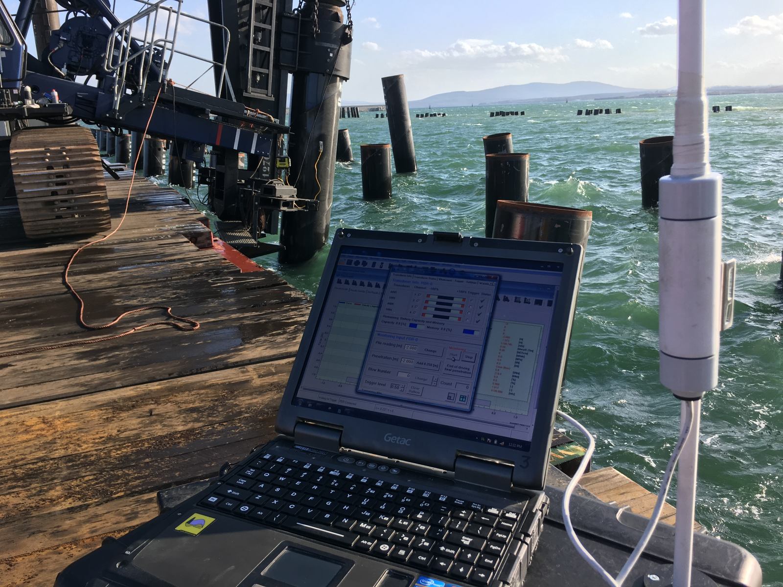
- Offshore pile monitoring: For large-diameter offshore piles, we provide real-time installation monitoring that tracks stress wave behaviour during driving, helping you identify changes in toe conditions as they happen.
- Independent technical review: If your project involves complex toe conditions, such as karst, variable rock, or uncertain plugging behaviour, we provide independent assessments and expert validation to support design decisions and reduce risk.
If you are working on a project where pile toe behaviour is a design or verification challenge, contact us to discuss how we can support your team with testing, analysis, or software solutions.