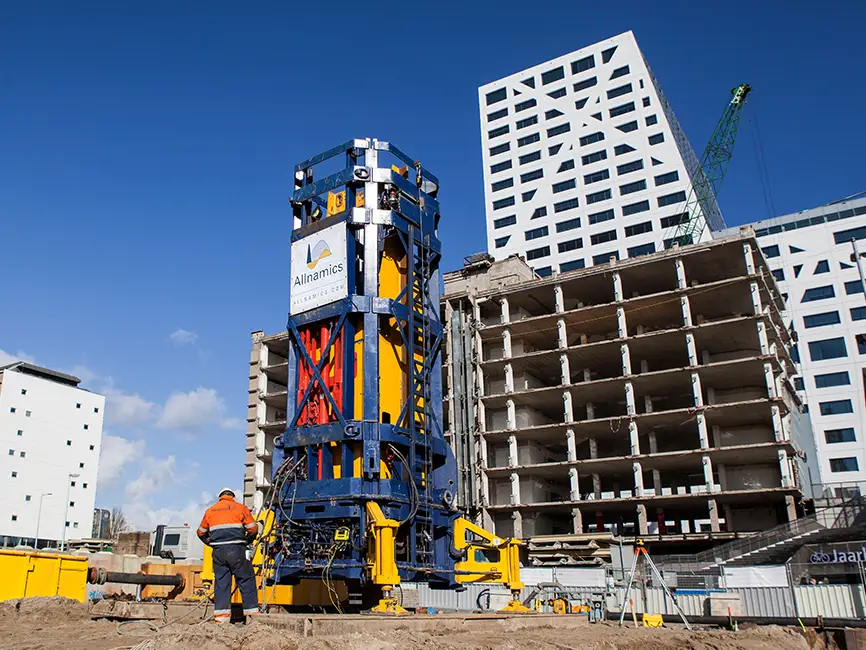
In a rapid load test, displacement is measured using velocity transducers or accelerometers mounted on the pile head, with displacement derived by integrating the velocity signal over time. Some setups also use laser sensors or displacement transducers for direct measurement. Because the load duration is short, accurate displacement measurement depends on high-quality instrumentation, precise timing, and careful signal processing to separate pile movement from noise and dynamic effects.
The sections below address the most common technical questions about how displacement is captured, interpreted, and compared to static test results in a rapid load test.
What instruments are used to measure displacement in Rapid Load Testing?
Displacement in a rapid load test is typically measured by integrating the output of velocity transducers or accelerometers attached to the pile head. These sensors record the velocity or acceleration of the pile during the load event, and displacement is then calculated numerically from that signal. In some configurations, laser displacement sensors or linear variable differential transformers (LVDTs) provide a direct displacement reference to verify the integrated result.
Force is measured simultaneously using a load cell or strain gauges mounted on the pile head. Together, the force and displacement signals form the raw dataset that all subsequent analysis depends on. The sensors must be capable of capturing a fast, high-amplitude event accurately, which means sampling rates are typically set in the range of several thousand readings per second.
Proper sensor mounting is important. Sensors that are poorly attached or misaligned introduce errors that propagate through the entire displacement calculation. In practice, at least two velocity or acceleration sensors are mounted symmetrically on the pile to detect and average out any bending or eccentric loading effects.
How does the short load duration affect displacement measurement accuracy?
The short load duration in a rapid load test, typically between 100 and 200 milliseconds, means that any error in the velocity or acceleration signal accumulates rapidly when integrated to produce displacement. A small offset or drift in the sensor signal can result in a significant error in the final displacement value, particularly at the end of the loading event where permanent set is assessed.
This is one reason why rapid load testing occupies a distinct category between dynamic load testing and static load testing. The load duration is long enough to reduce stress wave reflections within the pile, which simplifies the analysis compared to a dynamic load test. However, it is still short enough that the integration process must be handled carefully. Signal conditioning, baseline correction, and filtering are applied to the raw data before displacement values are accepted as reliable.
The pile’s inertia also plays a role. Because the pile accelerates and decelerates during the test, the measured force at the pile head is not the same as the force transferred to the soil. The inertia correction, which accounts for the pile’s own mass, must be applied before the displacement data can be used to interpret soil resistance. Without this correction, the apparent load-displacement relationship would overestimate resistance at peak force and underestimate it during the unloading phase.
What is the Unloading Point Method and how does it use displacement data?
The Unloading Point Method (UPM) is the most widely used analytical approach for deriving static pile capacity from rapid load test data. It uses the displacement, velocity, and force signals recorded during the test to separate the measured soil resistance into a static component and a rate-dependent (viscous) component, producing an equivalent static load-displacement curve.
The method identifies the point in the test where the pile velocity returns to zero, which is the unloading point. At this moment, the rate-dependent contribution to soil resistance is assumed to be zero, so the force at that instant represents the static resistance directly. From this reference point, the full static load-displacement curve is reconstructed by applying a damping model to the rest of the measured data.
Displacement data is central to this process in two ways. First, the displacement at the unloading point defines the pile’s permanent set and the mobilized resistance at that settlement level. Second, the shape of the displacement-time curve influences how the damping correction is applied across the loading event. If the displacement signal contains errors, the reconstructed static curve will be distorted, which is why signal quality and inertia correction must be confirmed before the UPM is applied.
It is worth noting that the UPM and related methods are not a simple conversion of peak measured force to static capacity. The maximum force recorded during a rapid load test includes inertia and viscous contributions that must be removed analytically. Treating the peak force as the pile’s static bearing capacity would overestimate actual performance.
How does RLT displacement data compare to Static Load Testing results?
When the test is correctly executed and the analysis is properly applied, the load-displacement curve derived from a rapid load test generally shows good agreement with results from a static load test on the same pile. However, the two methods measure fundamentally different things, and the comparison requires careful interpretation.
In a static load test, load and displacement are measured directly under quasi-static conditions. The pile-soil system has time to respond without rate effects, and the measured displacement at each load increment reflects genuine static settlement. In a rapid load test, the displacement is derived from an integrated velocity signal during a dynamic event, and the static-equivalent behavior is reconstructed analytically rather than observed directly.
The agreement between the two methods depends on several factors:
- Soil type: In granular soils, rate-dependent effects are generally smaller and the conversion from rapid to static response is more straightforward. In cohesive soils, loading rate effects on soil resistance can be significant, and the correction requires more careful calibration.
- Load level: If the rapid load test does not mobilize sufficient displacement to reach or approach failure, the load-displacement curve cannot be reliably extrapolated to determine ultimate capacity. Standards including ISO 22477-10 and NEN 7201:2025 set explicit limits on extrapolation in such cases.
- Analysis model: Different damping models and rate-correction approaches produce different results. The choice of model should reflect the pile type, soil profile, and available reference data.
Comparison programs, where rapid load tests and static load tests are performed on the same pile or site, have been used extensively to validate and calibrate the method. These programs form the empirical foundation that supports the use of rapid load testing as a practical alternative to static testing in many project contexts.
What factors can distort displacement readings during a Rapid Load Test?
Several factors can introduce errors into the displacement readings recorded during a rapid load test. The most common sources of distortion are sensor signal drift, integration errors, eccentric loading, and inadequate inertia correction.
Signal drift occurs when the velocity or acceleration sensor does not return to a true zero baseline after the load event. When this drifted signal is integrated, the cumulative error produces an incorrect permanent displacement value. Baseline correction procedures are applied to address this, but they require judgment and can introduce their own uncertainty if not handled carefully.
Eccentric loading, where the applied force is not perfectly aligned with the pile axis, causes the pile head to rotate slightly during the test. Sensors mounted on one side of the pile will record a combination of axial movement and rotation, which distorts the displacement signal. Using two sensors mounted symmetrically and averaging their outputs reduces this effect.
Inertia correction is another important source of potential error. If the pile mass or its distribution is not accurately known, the correction applied to separate pile inertia from soil resistance will be incorrect. This affects not only the force-displacement relationship but also the displacement value at the unloading point, which anchors the entire UPM analysis.
In cohesive soils, rate-dependent soil behavior adds a further layer of complexity. The soil resistance mobilized during the short load duration of a rapid load test can be higher than the resistance that would be mobilized under static loading at the same displacement. If this rate effect is not corrected appropriately, the derived static capacity will be overestimated. No single universal correction factor applies across all cohesive soil conditions, and the appropriate approach depends on soil type, pile type, and the analytical framework being used.
How Allnamics Supports Rapid Load Testing and Displacement Analysis
We have been involved in the development and application of rapid load testing for decades, and our team brings that depth of experience directly to your project. When displacement measurement accuracy and reliable capacity interpretation matter, we provide the instrumentation, analysis, and expert judgment your project needs.
Here is what we offer for rapid load testing projects:
- Full test execution: We deploy and operate the StatRapid system, our in-house developed rapid load test installation, capable of testing pile resistances in the range of 8 to 16 MN without the need for a large static reaction structure.
- High-quality instrumentation: We use calibrated force and velocity sensors with appropriate sampling rates, mounted and verified to minimize eccentric loading effects and signal drift.
- Inertia correction and signal processing: Our engineers apply rigorous signal processing and pile mass corrections before any displacement or capacity values are reported.
- Unloading Point Method analysis: We apply the UPM and, where appropriate, alternative analytical methods suited to the specific soil and pile conditions on your site.
- Rate-effect assessment for cohesive soils: Where loading rate effects are relevant, we evaluate the appropriate correction approach based on soil type, available reference data, and applicable standards including ISO 22477-10 and NEN 7201:2025.
- Comparison with static test results: Where project requirements call for it, we can design and execute comparison programs to validate rapid load test results against static load testing on the same site.
If you want to discuss how rapid load testing fits your foundation verification program, contact our team and we will help you assess the right approach for your pile type, soil conditions, and project requirements.