

Soil resistance increases as a pile penetrates deeper because more soil surface area contacts the pile shaft, the stress state around the pile changes, and the pile tip encounters progressively denser or stronger material. Two mechanisms drive this: skin friction accumulates along the growing shaft length, and end bearing responds to the strength of the soil directly beneath the tip. Understanding how these mechanisms interact is important for accurate drivability predictions and safe pile installation.
The relationship between penetration depth and resistance is not simply linear. Friction fatigue, soil layering, pore pressure changes, and time-dependent effects all shape the resistance profile that your team will encounter during installation. The sections below answer the most common questions about each of these mechanisms.
What causes soil resistance to act on a pile during driving?
Soil resistance during pile driving comes from two sources: shaft friction acting along the pile’s lateral surface and end bearing acting at the pile tip. Together these form the total Soil Resistance to Driving (SRD). During dynamic loading, a third component also appears: velocity-dependent resistance caused by rapid soil deformation, which does not contribute to long-term static capacity.
When a hammer strikes the pile head, a stress wave travels down the pile and mobilizes the surrounding soil. The soil responds through a combination of elastic deformation and plastic displacement. The portion of resistance that involves permanent soil displacement is what drives the pile downward with each blow. The portion that is purely elastic springs back and is not useful for penetration.
It is important to distinguish between static soil resistance and dynamic soil resistance. Static resistance exists both during driving and under long-term load, so it contributes to the pile’s eventual bearing capacity. Dynamic resistance arises only from rapid movement and disappears under static conditions. A high total resistance during driving does not automatically mean a correspondingly high static foundation capacity. This distinction sits at the heart of reliable soil modelling for pile driving.
Why does skin friction increase as the pile goes deeper?
Skin friction increases with depth primarily because the pile shaft contacts a larger area of soil as penetration grows, and because horizontal effective stress, which governs how tightly the soil grips the shaft, generally increases with depth. More contact area combined with higher normal stress produces greater total frictional resistance along the shaft.
However, the relationship is more complex than a simple linear accumulation. A well-documented phenomenon called friction fatigue, also referred to as friction degradation, means that the local shaft friction at any given depth does not remain constant as the pile continues to advance. Once the pile tip passes a particular soil horizon, that horizon experiences repeated loading cycles. With each additional cycle, the local shear resistance at that horizon tends to decrease toward a residual value.
Research by Alm and Hamre, based on back-analysis of offshore installations across multiple North Sea locations, showed that the transition from initial to residual shaft friction follows an exponential decay pattern. In normally consolidated clay, residual friction may be reached after roughly 30 metres of additional pile penetration past a given horizon. In heavily overconsolidated clay, that transition can occur within as little as 10 metres. In sand, the transition typically falls in the range of 20 to 30 metres of further penetration.
This means that models which assume a uniform shaft friction along the full pile length will overestimate resistance near the tip and underestimate the degraded friction higher on the shaft. For long piles, particularly offshore piles reaching 75 metres or more, ignoring friction fatigue can lead to significant errors in predicted blow counts and installation performance.
How does end bearing change with pile tip depth?
End bearing changes with pile tip depth because the strength and stiffness of the soil directly beneath the tip change as the tip moves into new material. In general, end bearing increases as the tip enters denser or stronger layers, and it can drop sharply when the tip moves from a strong layer into a weaker one. The tip resistance is highly sensitive to the soil conditions within a few pile diameters of the current tip position.
For open-ended steel pipe piles, common in offshore applications, the question of whether the pile behaves as plugged or unplugged adds another layer of complexity. An unplugged pile mobilizes end bearing only on the annular steel area at the tip, while a plugged pile mobilizes bearing across the full internal cross-section. The Alm and Hamre model treats offshore open pipe piles as unplugged for the purpose of SRD calculation, which is conservative for tip resistance but reflects observed behaviour during driving.
In clay, tip resistance is typically expressed as a multiple of the undrained shear strength. In sand, it correlates with cone resistance from a CPT. Because the tip is always advancing into undisturbed soil, end bearing does not experience the same fatigue degradation as shaft friction. The tip resistance at any depth reflects the current soil state at that depth, making CPT data a particularly useful input for predicting how end bearing will evolve through the soil profile.
What is soil setup and how does it affect resistance after driving?
Soil setup is the increase in pile resistance that occurs after driving stops. During installation, the soil around the pile is disturbed and remoulded, and in saturated fine-grained soils, excess pore water pressures build up. Once driving ceases, those pore pressures dissipate, the soil reconsolidates around the pile shaft, and effective stresses recover, sometimes exceeding pre-installation values. The result is a pile that is significantly harder to redrive days or weeks after initial installation.
Setup is most pronounced in soft to medium clays and silts, where pore pressure dissipation is slow and the remoulding effect during driving is large. In dense sands, setup is typically smaller and occurs more quickly because drainage is faster. The practical consequence for installation planning is that a pile left in place overnight or over a weekend may require substantially more energy to advance further, a factor that must be accounted for when scheduling installation sequences.
The inverse effect, relaxation, can occur in some dense sands and weak rocks, where driving-induced dilation causes negative pore pressures that temporarily inflate resistance during driving. When those pressures equalize, resistance drops. Distinguishing between setup and relaxation requires site-specific knowledge and, where possible, redriving tests to measure actual resistance change over time.
How does soil layering affect resistance along the pile shaft?
Soil layering creates a non-uniform resistance profile along the pile shaft because different soil types contribute different levels of friction and because the pile tip response changes abruptly when crossing layer boundaries. A pile passing through alternating sand and clay layers will experience varying local friction at each horizon, and the tip will see step changes in end bearing as it crosses from one material to another.
Layering also interacts with friction fatigue in a depth-dependent way. Consider a pile driven through an upper sand layer into a deeper clay layer. The sand at the top of the profile has experienced many more loading cycles than the clay near the current tip. The residual friction in the upper sand may be substantially lower than its initial value, while the clay near the tip is still mobilizing close to its peak resistance. A realistic SRD profile must capture this variation rather than applying a single degradation factor uniformly along the shaft.
For vibratory driving, layering effects are particularly important. At a frequency of around 23 Hz, a vibratory hammer produces roughly 10,000 cycles in approximately seven minutes. Soil near the top of the profile accumulates the full loading history, while soil adjacent to the current tip has experienced far fewer cycles. Applying a single beta factor, the ratio of residual to initial soil strength, uniformly across the entire shaft is physically unrealistic for long piles installed with a vibratory hammer. Advanced soil modelling for pile driving treats fatigue as a function of local loading history at each depth increment.
How is changing soil resistance measured during pile installation?
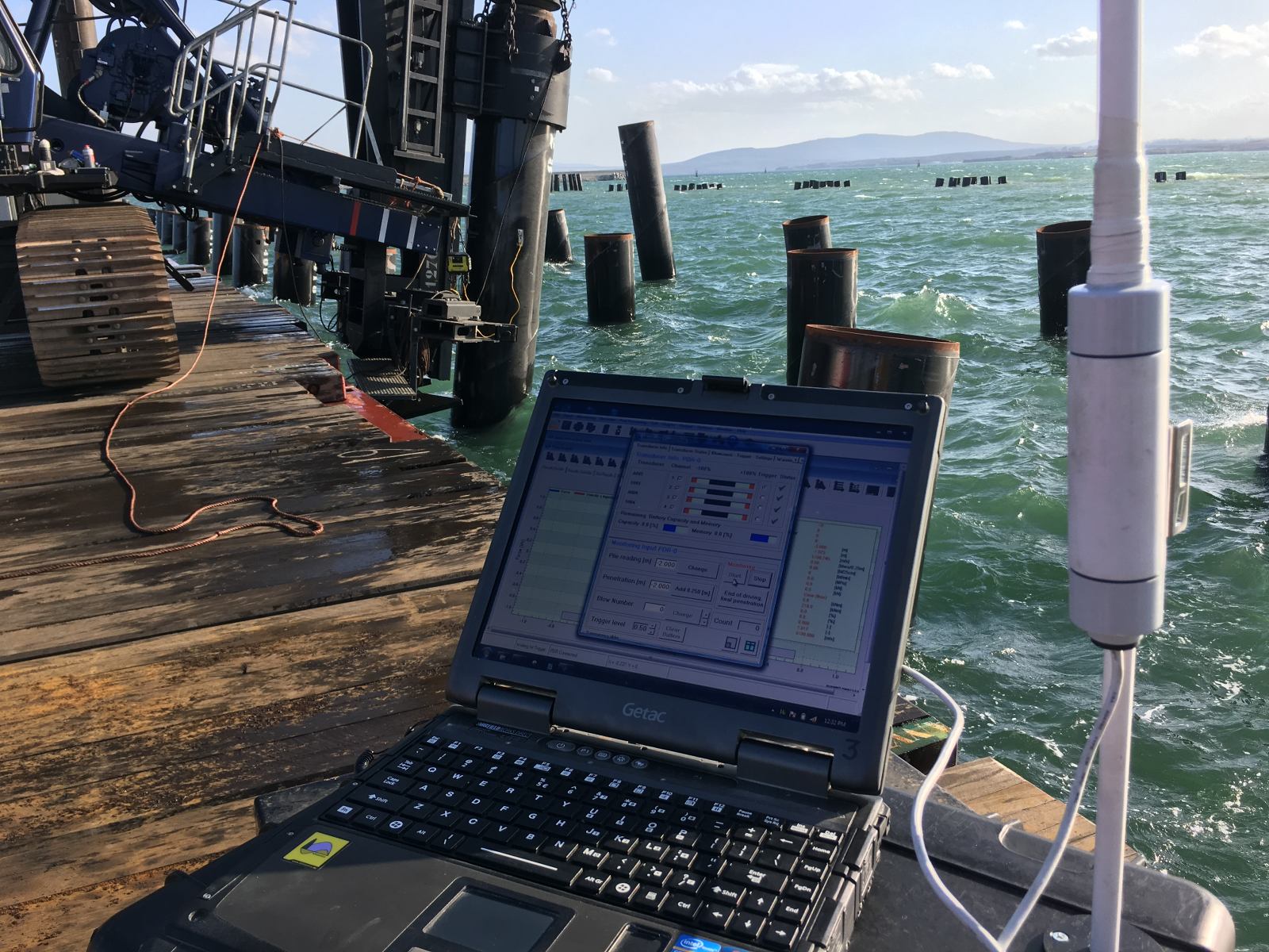
Changing soil resistance during pile installation is measured primarily through dynamic load testing and pile driving analysis (PDA), which use strain gauges and accelerometers attached near the pile head to record force and velocity signals during each hammer blow. Signal matching software then back-calculates the soil resistance distribution along the pile at that moment of driving.
The blow count, the number of hammer blows required to advance the pile a set distance, provides a continuous indirect indicator of resistance throughout installation. A rising blow count signals increasing resistance; a sudden drop may indicate the pile tip has entered a weaker layer or that friction fatigue has significantly reduced shaft resistance. However, blow count alone cannot separate shaft friction from end bearing, and it is influenced by hammer performance and energy transfer as well as soil resistance.
A complete picture of how resistance evolves with depth comes from combining field measurements with pre-installation predictions. A driveability profile versus penetration depth, rather than a single calculated blow count, gives your team a reference against which measured installation behaviour can be compared at every stage. Deviations from the predicted profile can flag unexpected soil conditions, equipment issues, or the onset of refusal risk before they become critical problems.
For vibratory driving, continuous monitoring of penetration rate, current draw, and vibration amplitude provides analogous information. Because vibratory installation does not produce discrete blows, the equivalent indicator is the rate of penetration relative to the applied eccentric moment and frequency: a slowing penetration rate under constant settings points to increasing soil resistance.
How Allnamics Supports Drivability Predictions and Soil Resistance Analysis
We combine decades of experience in pile installation mechanics with in-house software and field measurement capabilities to give your team a reliable picture of how soil resistance will behave throughout the installation process. Our approach covers both the prediction phase before installation begins and the measurement phase during driving.
- Drivability predictions using AllWave-PDP and AllWave-VDP: Our AllWave software package simulates hammer, pile, and soil interaction for both impact and vibratory driving. Outputs include blow count versus penetration depth, maximum compression and tension stresses, energy transfer, and refusal risk, giving you a full installation performance profile, not just a single number.
- CPT-based soil modelling for pile driving: We translate CPT, SPT, and laboratory data into depth-dependent SRD profiles that account for friction fatigue, layer transitions, and the distinction between static and dynamic resistance components.
- Friction fatigue and setup modelling: We apply physically realistic models that treat degradation as a function of local loading history at each depth, avoiding the errors that come from applying uniform beta factors to long piles.
- Dynamic load testing and PDA during installation: Our field teams instrument piles with strain gauges and accelerometers to measure actual resistance distribution during driving, allowing real-time comparison against predicted profiles.
- Vibratory driving analysis: We model the specific challenges of vibratory installation, including cycle-dependent fatigue accumulation and the difference in resistance behaviour between granular and cohesive soils.
- Independent technical review: We provide expert review of existing drivability studies, SRD profiles, and installation records for projects where a second opinion adds value before or after installation.
If your project involves complex soil conditions, long offshore piles, or installation methods where resistance behaviour is uncertain, we can help you build a more accurate and defensible prediction. Contact us to discuss your project and find out how our drivability and soil modelling services can reduce your installation risk.