The CASE method is a real-time calculation technique used in dynamic pile testing to estimate the static bearing capacity of a pile directly from measurements taken during hammer impact. It uses strain and acceleration data recorded at the pile head to compute a capacity value within seconds, making it one of the fastest tools available for pile capacity assessment during driving or restrike. The sections below unpack how the calculation works, what equipment it requires, and where it fits alongside more advanced analysis methods.
How does the CASE method calculate pile bearing capacity?
The CASE method calculates pile bearing capacity by combining force and velocity measurements recorded at the pile head during a hammer blow. Using stress wave theory, it separates the total resistance acting on the pile into static and dynamic components. The static component, which represents the bearing capacity you want to know, is extracted by applying a damping correction to the measured total resistance.
When a hammer strikes a pile head, a compressive stress wave travels down the pile and reflects back upward. Sensors mounted near the pile head record both the force (derived from strain measurements) and the particle velocity (derived from accelerometer measurements) throughout this event. The CASE method uses these two signals at two specific moments in time: the moment of peak force and a time equal to one full wave travel time later.
The core formula combines these values and subtracts a damping term that accounts for velocity-dependent soil resistance. The result is an estimate of the static pile capacity, often referred to as the CASE capacity or Rc. Because the calculation runs in real time during the test, engineers can monitor capacity estimates blow by blow as driving progresses.
This real-time feedback is one of the method’s most practical advantages. During a restrike test, for example, your team can immediately see whether the pile has gained capacity through soil setup and whether full resistance has been mobilized by the applied energy.
What equipment is used in a CASE method test?
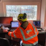
A CASE method test uses the same instrumentation as any dynamic load test: strain transducers and accelerometers bolted to the pile shaft near the pile head, connected to a data acquisition unit that records, processes, and displays the measurements in real time. The hammer used for installation or a separate drop hammer provides the impact energy.
The sensors are typically mounted in pairs on opposite sides of the pile to account for any eccentricity in the hammer blow. The strain transducers measure deformation of the pile material, from which force is calculated using the pile’s cross-sectional area and elastic modulus. The accelerometers measure particle acceleration, which is integrated over time to obtain velocity.
The data acquisition unit converts these raw signals into force and velocity traces and applies the CASE formula continuously. Modern systems display the calculated capacity value on screen after each blow, allowing the engineer to track trends across multiple hammer strikes. For driven piles, this equipment attaches directly to the pile during installation, so no additional mobilization is needed beyond what the driving operation already requires.
Reliable results depend on well-maintained, calibrated sensors and a data acquisition system operated by an experienced engineer. Equipment condition and correct sensor installation directly affect the quality of the force and velocity signals, and poor signal quality will propagate directly into the capacity estimate.
What is the CASE damping factor and how is it chosen?
The CASE damping factor, commonly written as Jc, is a dimensionless coefficient that controls how much of the measured total resistance is attributed to dynamic (velocity-dependent) soil damping rather than static bearing capacity. Choosing the right Jc value is the most important and most uncertain step in applying the CASE method.
Dynamic soil resistance increases with the speed at which the pile moves through the soil during impact. The CASE formula removes this velocity-dependent component by multiplying Jc by the pile impedance and the velocity at the pile toe. A higher Jc value removes more dynamic resistance, resulting in a lower static capacity estimate. A lower Jc value retains more of the measured resistance as static, producing a higher estimate.
The damping factor is not measured directly during the test. Instead, it is selected based on the soil type at the pile toe, guided by correlations developed from decades of comparative testing between dynamic and static load tests. Typical guidance associates lower Jc values with clean granular soils such as sand and gravel, and higher values with cohesive soils such as clay and silt. However, these are ranges rather than fixed values, and the appropriate choice depends on the specific soil conditions at each site.
This dependence on an assumed Jc is the CASE method’s most significant limitation. If the damping factor is poorly chosen, the capacity estimate can be substantially wrong in either direction. For this reason, the CASE method works best when Jc has been calibrated against a static load test or a signal matching analysis on the same site or in comparable soil conditions.
What is the difference between the CASE method and CAPWAP?
The CASE method and CAPWAP (or equivalent signal matching software such as AllWave-DLT) both use the same field measurements, but they differ fundamentally in how they process those measurements. The CASE method applies a closed-form formula in real time; signal matching is an iterative numerical analysis performed after the test.
In the CASE method, a single damping factor is assumed and applied to the measured signals to produce an immediate capacity estimate. The calculation is fast and transparent, but it depends entirely on the assumed Jc value and provides no information about how resistance is distributed along the pile shaft and at the toe.
Signal matching takes a fundamentally different approach. The engineer builds a numerical model of the pile and soil system, then adjusts the model parameters iteratively until the calculated force response matches the measured response. When a good match is achieved, the model yields not only total capacity but also the distribution of shaft friction and toe resistance, as well as information about pile integrity. This process requires more time and engineering judgment, but it produces a more complete and generally more reliable result.
In practice, the two methods are used together rather than as alternatives. The CASE method provides real-time feedback during the test, helping the engineer confirm that sufficient energy was applied and that the pile responded as expected. Signal matching is then performed on selected blows after the test to produce the final, defensible capacity assessment. Treating CASE results as a standalone final answer, without signal matching verification, increases the risk of significant error.
When should the CASE method be used instead of static load testing?
The CASE method, as part of pile load testing and capacity verification, is most appropriate when you need rapid capacity verification across a large number of driven piles in granular soils, and when load-settlement behavior is not the primary design requirement. It is not a direct replacement for static load testing in all situations.
Dynamic testing with CASE analysis fits well in the following scenarios:
- Driven piles in sand or gravel where end-bearing dominates and soil damping is well understood
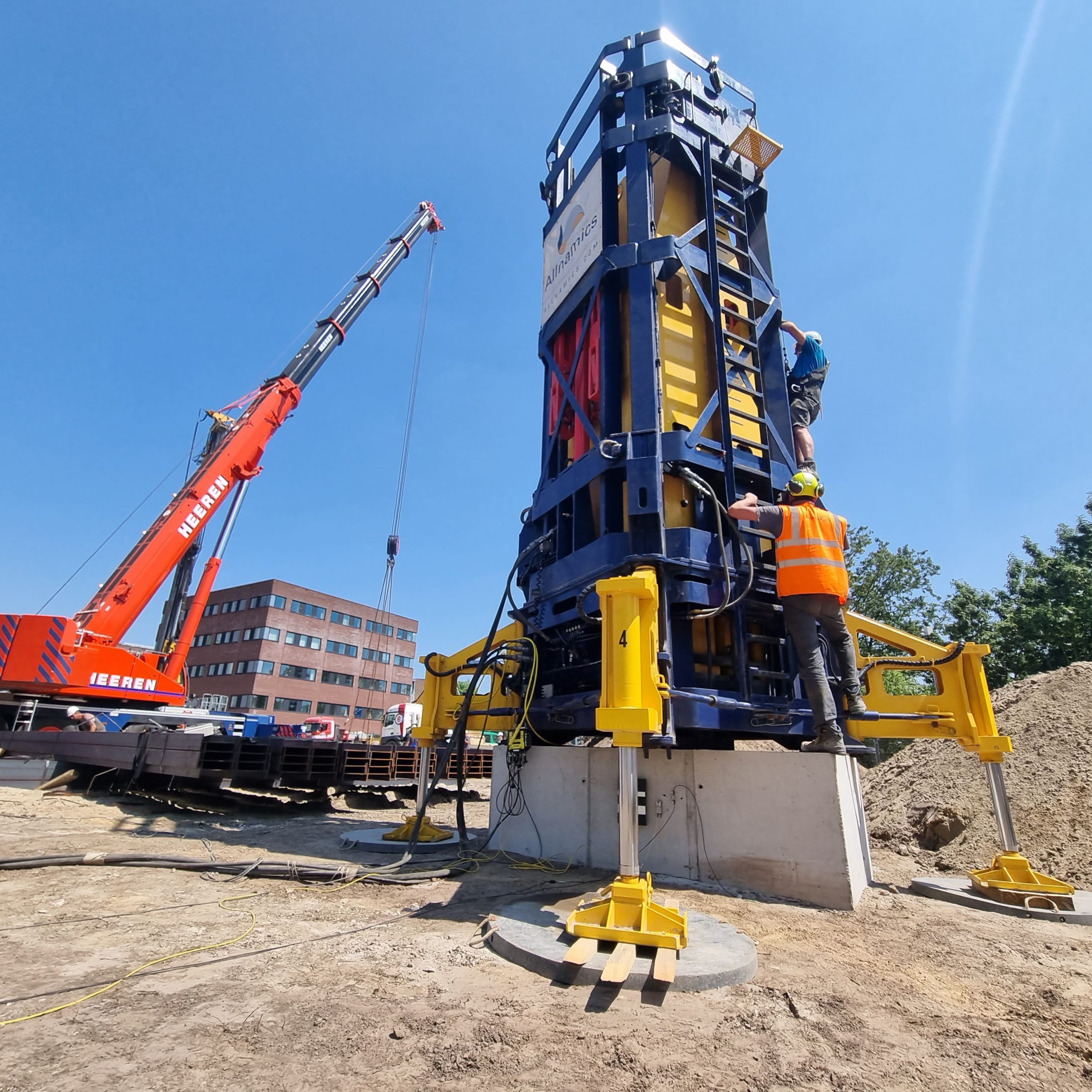
- Offshore foundations where performing a static load test underwater is logistically impractical or impossible
- Quality control programs where a large number of production piles need capacity checks after a smaller number of reference tests have been conducted
- Large infrastructure projects where testing efficiency and speed are important constraints
- Restrike testing to confirm that soil setup has occurred and that the pile has reached its target long-term capacity
Static load testing remains the preferred method when load-settlement behavior governs the design, when piles are bored or cast in situ with variable cross-sections, when the soil profile includes thick layers of soft clay, or when regulatory requirements specifically call for it. Many projects combine both approaches: static or Rapid Load Testing on a small number of trial piles, and dynamic testing for broader quality control across the production program.
How reliable are CASE method results in practice?
CASE method results are most reliable for end-bearing driven piles in granular soils when the damping factor has been properly calibrated. Under these favorable conditions, dynamic load testing can produce capacity estimates within 10 to 20 percent of static load test results. In less favorable conditions, the uncertainty grows considerably.
Several factors directly affect how reliable a CASE result will be:
- Soil type at the pile toe: Granular soils produce more consistent damping behavior and better correlation with static results. Cohesive soils introduce greater uncertainty, and dynamic testing should generally be approached with caution in predominantly clay profiles.
- Setup time: For driven piles, testing at restrike after sufficient time has passed allows pore pressures to dissipate and soil resistance to recover to its long-term static value. Testing too soon after driving will underestimate capacity.
- Applied energy: The hammer blow must deliver enough energy to fully mobilize soil resistance. Insufficient energy leads to underestimation of capacity regardless of how well the CASE formula is applied.
- Pile type and geometry: Steel piles with uniform cross-sections produce clean, interpretable signals. Bored or cast-in-situ concrete piles with variable geometry and material properties make stress wave analysis considerably harder and reduce result reliability.
- Jc calibration: An uncalibrated damping factor introduces a systematic bias that cannot be detected from the CASE output alone.
Because dynamic tests can both overestimate and underestimate pile capacity, appropriate safety factors must always be applied to CASE-based results. The method works best as part of a broader dynamic load testing program that includes signal matching analysis and, where the project warrants it, correlation against at least one static or Rapid Load Test.
How We Support Dynamic Pile Testing and CASE Analysis
At Allnamics, we have been involved in the development and application of dynamic pile testing methods for decades. Our founders played a direct role in advancing the field, and that depth of experience shapes how we approach every project. When you work with us on a dynamic load testing program, you get more than raw data.
- Field testing with calibrated equipment: We use our own purpose-built monitoring systems, including the Allnamics PDR, to collect high-quality strain and acceleration data during driving or restrike operations, onshore and offshore.
- Real-time CASE analysis: Our engineers monitor CASE capacity estimates blow by blow during the test, giving your team immediate feedback on pile performance and energy delivery.
- Signal matching with AllWave-DLT: After the test, we perform rigorous signal matching analysis using AllWave-DLT to produce a defensible, calibrated capacity assessment that goes well beyond what the CASE formula alone can provide.
- Independent interpretation: We provide expert judgment on damping factor selection, setup time, and result reliability, tailored to your specific pile type, soil conditions, and project requirements.
- Combined testing programs: Where your project requires it, we combine dynamic testing with Static Load Testing or Rapid Load Testing to give you the most complete picture of foundation performance.
If you want to understand what dynamic pile testing can and cannot tell you about your foundations, and how to get the most reliable results from your testing program, contact our pile testing team directly. We are ready to help you design a testing approach that fits your project conditions and gives you confidence in your foundation performance.