

Thin soil layers create unpredictable resistance during pile driving because they introduce abrupt, localized changes in Soil Resistance to Driving (SRD) that standard uniform-profile models often fail to capture accurately. A pile transitioning through a thin hard layer, a soft interlayer, or a dense sand lens can experience sudden refusal, unexpected tension stresses, or premature penetration loss within a matter of centimeters. The sections below address the most common questions engineers face when thin layers are part of the soil profile.
Why do thin soil layers create unpredictable resistance during driving?
Thin soil layers create unpredictable resistance because the pile tip and shaft interact with multiple soil types almost simultaneously, and the transition between them happens faster than a standard blow-by-blow analysis can resolve. The result is a rapid, localized shift in both toe resistance and shaft friction that does not follow the gradual trend a uniform soil model would predict.
The core mechanism is the mismatch between the thickness of the layer and the wavelength of the stress wave traveling through the pile. When a layer is thin relative to the stress wave’s wavelength, the reflected wave from the layer boundary arrives back at the pile head before the driving system has completed a single cycle. This compresses the effective response window and makes the resistance signal difficult to interpret in real time.
Friction fatigue adds another layer of complexity. As the pile advances, the shaft friction at any given depth is not fixed: it depends on how many loading cycles that soil element has already experienced. A thin dense layer near the surface may have undergone thousands of cycles by the time the pile tip reaches its target depth, reducing its contribution to total shaft resistance significantly. Models that assign a single static friction value to each layer miss this progressive degradation entirely, which is why CPT-based soil modeling for pile driving that accounts for local loading history produces more reliable SRD profiles.
What types of thin soil layers are most problematic for pile drivability?
The most problematic thin layers for pile drivability are dense sand or gravel lenses within soft clay, cemented or calcified horizons, chalk interlayers, and soft clay seams within dense sand. Each creates a different failure mode, and none of them behave the way a simple interpolation between adjacent layers would suggest.
Dense sand lenses embedded in soft clay concentrate toe resistance over a very short penetration interval. The pile tip load spikes sharply, then drops as the tip exits the lens, creating a stress pattern that can exceed design limits even if the average resistance over the full profile appears acceptable.
Chalk deserves special attention. Low-to-medium density chalk shows highly variable field behavior: both refusal and near-unimpeded penetration have been recorded at similar sites. Traditional SRD methods frequently diverge from actual installation performance in chalk because the material’s response depends on effective stress, interface shear characteristics, and the progressive degradation of local resistance as driving continues. Treating chalk as a standard sand or clay case leads to unreliable predictions.
Soft clay seams within dense sand create the opposite problem: a sudden local drop in resistance that can cause the pile to run (advancing faster than the hammer can control) before resistance rebuilds at the next competent layer. This can generate tension stresses in the pile shaft that are difficult to anticipate without explicit layer-by-layer simulation.
How does a thin hard layer cause pile refusal or damage?
A thin hard layer causes pile refusal when the toe resistance it generates exceeds the net driving force the hammer can deliver at that penetration depth. It causes pile damage when the compressive stress at the pile tip, or the tension stress reflected back up the shaft, exceeds the structural capacity of the pile material, even if the pile eventually penetrates the layer.
The stress wave mechanism is central to understanding both outcomes. When the pile tip strikes a hard layer, a large compressive stress wave reflects back up the shaft. If the layer is thin, the tip may partially penetrate and then encounter a softer zone below, generating a second reflection of opposite sign. This sequence can produce tension stresses in the upper shaft that are large enough to crack concrete piles or initiate fatigue damage in steel sections.
Refusal risk increases when the blow count climbs steeply over a short penetration interval. A hammer that operates within its rated limits on the approach to the hard layer may reach its operational boundary (maximum rated energy or minimum acceptable penetration per blow) before the pile clears the layer. Selecting a more powerful hammer to overcome the layer can resolve the penetration problem while simultaneously pushing compressive stresses beyond acceptable limits. This is why hammer selection can never be based on maximum penetration alone: both drivability and pile integrity must be evaluated together across the full installation profile.
How can drivability studies predict the impact of thin layers before installation?
Drivability studies predict the impact of thin layers by simulating the complete hammer-pile-soil interaction at each penetration increment, producing blow count, stress, and energy transfer profiles that reveal where resistance spikes, tension peaks, or refusal risk occur before a single pile is driven on site.
The quality of the prediction depends directly on the resolution of the soil model. A CPT-based approach that links drivability parameters directly to measured cone resistance values, rather than to interpreted parameters like undrained shear strength, reduces the uncertainty introduced by intermediate interpretation steps. Where the CPT log captures a thin dense layer clearly, the drivability model can represent its effect on toe resistance and shaft friction at that specific depth.
A complete drivability analysis for a profile containing thin layers should report at minimum:
- Blow count versus penetration depth, showing the rate of change through each layer transition
- Maximum compressive and tensile stresses at critical depths, not just at the pile tip
- Energy transfer efficiency across the full installation sequence
- Refusal risk depth, identifying where blow count may reach practical limits
- Installation time estimate, including the effect of reduced penetration rate through hard layers
Friction fatigue must be modeled as a function of local loading history rather than as a uniform reduction factor applied to the whole shaft. Soil near the pile head has experienced far more cycles than soil near the current tip position, and a realistic model reflects that difference. The AllWave software package supports this type of layer-by-layer simulation for both impact and vibratory driving scenarios.
What monitoring methods detect thin layer effects during pile driving?
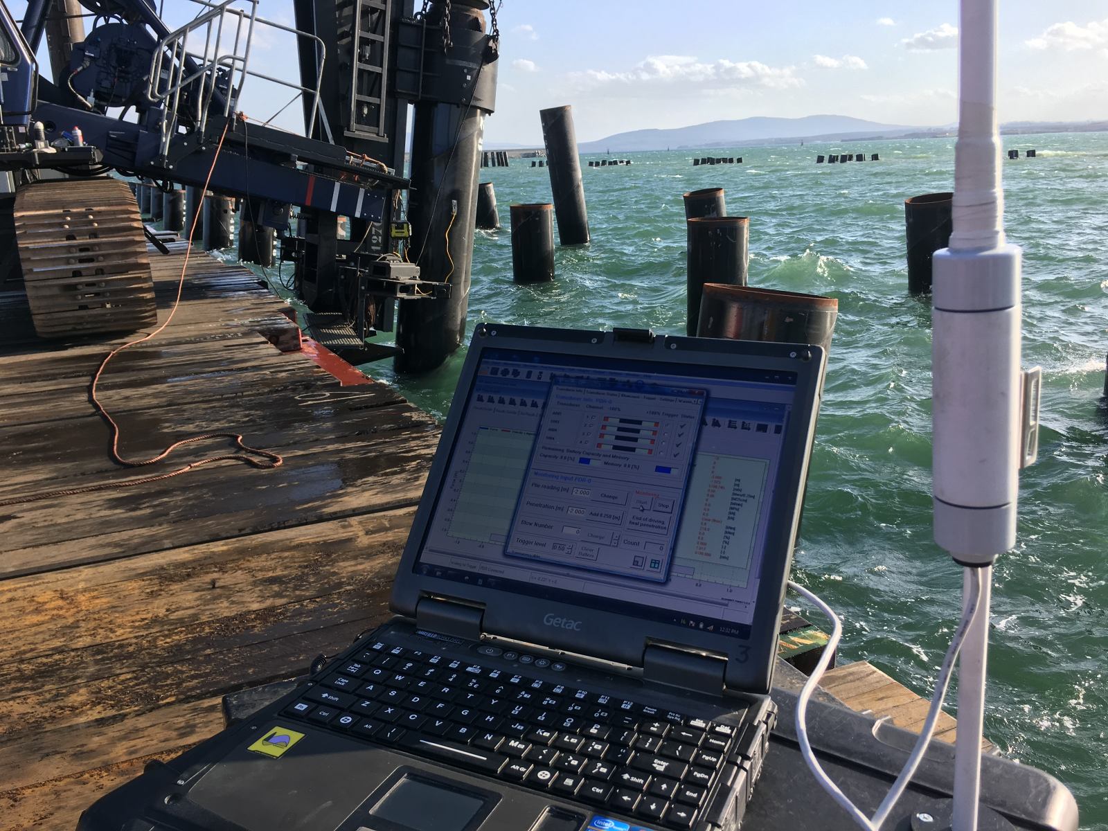
The most direct method for detecting thin layer effects during pile driving is Dynamic Load Testing (DLT) with real-time signal matching, which measures force and velocity at the pile head on every blow and allows engineers to identify sudden changes in resistance distribution as the pile advances through the profile.
During impact driving, the stress wave signal recorded at the pile head carries information about what is happening at the tip and along the shaft. A sharp increase in toe resistance as the pile enters a hard layer, or a tension wave reflected from a soft interlayer, appears in the force-velocity record within milliseconds of the blow. Experienced analysts can identify these signatures in real time and adjust driving energy or pause installation if stress limits are approached.
Blow count monitoring, tracking penetration per blow continuously, provides a simpler but still useful signal. A sudden increase in blow count over a short depth interval is a reliable indicator that the pile tip has entered a harder layer. Combined with the known CPT profile, this allows the site team to anticipate how long the resistance spike will last and whether the hammer has sufficient capacity to drive through it.
For vibratory driving, penetration rate monitoring serves a similar function. A drop in penetration rate per unit time, without a change in hammer settings, indicates increased resistance, often associated with a layer transition. Monitoring the amplitude of pile motion alongside penetration rate helps distinguish between a genuine resistance increase and a change in soil-pile coupling behavior.
When should thin soil layers trigger a redesign of the piling strategy?
Thin soil layers should trigger a redesign of the piling strategy when the drivability analysis shows that the available hammer cannot drive the pile through or past the layer without exceeding structural stress limits, or when the predicted blow count at the layer reaches refusal before the target penetration depth is achieved.
A redesign is also warranted when the layer creates a situation where the pile can technically penetrate but only at the cost of fatigue damage accumulated over many high-stress blows. The number of stress cycles at elevated amplitude matters for long-term pile integrity, particularly for steel piles in offshore environments where fatigue life is a design constraint.
Practical redesign options depend on the specific layer geometry and soil conditions:
- Pre-drilling or pre-augering through the hard layer before driving, reducing the resistance the hammer must overcome
- Changing pile type or wall thickness to increase structural capacity at the critical depth
- Switching from impact to vibratory driving for part of the installation, where the cyclic disturbance of vibratory driving reduces shaft friction and allows the pile to advance through granular interlayers more efficiently
- Adjusting target penetration depth if the layer is thin and the bearing capacity above it is sufficient to meet design requirements
- Selecting a different hammer with a stroke and energy profile better matched to the resistance pattern, while verifying that stress limits remain acceptable at the new energy level
The decision to redesign should be based on a revised drivability study that models the proposed change explicitly, not on field judgment alone. A layer that appears manageable in a simplified analysis can behave very differently when friction fatigue, stress wave reflections, and hammer-soil interaction are modeled at full resolution.
How Allnamics Helps with Pile Drivability in Complex Soil Profiles
We work with project teams at the planning stage and during installation to identify, quantify, and manage the risks that thin soil layers introduce into pile driving operations. Our approach combines advanced simulation, CPT-based soil modeling, and field monitoring to give you a complete picture of installation behavior before and during driving.
Here is what we provide:
- Drivability studies using AllWave-PDP and AllWave-VDP: layer-by-layer simulation of impact and vibratory driving that captures blow count, stress profiles, energy transfer, and refusal risk at every penetration increment, including thin hard or soft layers
- CPT-based soil modeling: direct linkage between measured cone resistance and drivability parameters, reducing uncertainty from intermediate interpretation and improving prediction accuracy in variable profiles
- Friction fatigue modeling: realistic representation of how shaft resistance changes along the pile as a function of local loading history, not a uniform reduction factor
- Dynamic Load Testing during installation: real-time force and velocity measurements that detect layer-driven resistance changes blow by blow, with signal matching to identify stress distribution along the shaft
- Hammer selection review: evaluation of compressive and tensile stresses across the full installation sequence to confirm that the selected hammer drives the pile to target depth without exceeding structural limits
- Redesign support: if thin layers create refusal or damage risk, we model alternative strategies including pre-drilling, pile geometry changes, or driving method adjustments and provide a revised drivability assessment
If your project involves a soil profile with thin layers that could affect installation performance, contact us to discuss a drivability study tailored to your site conditions and pile design.