Offshore pile driving energy transfer is monitored using strain gauges and accelerometers attached to the pile, which measure force and velocity signals at the pile head during each hammer blow. These measurements feed into wave equation analysis to quantify how much of the hammer’s energy actually reaches the pile and drives it into the soil. The sections below address the most common technical questions about how this monitoring works in practice.
What equipment is used to measure energy transfer during offshore pile driving?
The core instruments for measuring energy transfer during offshore pile driving are strain gauges and accelerometers mounted at or near the pile head. Strain gauges measure the compressive force wave generated by each hammer impact, while accelerometers capture the velocity of the pile head. Together, these two signals allow engineers to calculate the energy actually transmitted into the pile during installation.
In practice, the sensors are attached in pairs on diametrically opposite sides of the pile to account for any bending or eccentric loading. The raw signals from the sensors are fed in real time to a data acquisition unit on the installation vessel. Systems such as the PDR data acquisition unit are designed specifically for this environment, combining intelligent sensors with robust signal processing suited to the noise, vibration, and weather conditions encountered offshore.
The data acquisition unit records force and velocity traces for every hammer blow. Engineers review these traces continuously during driving to track energy transfer, monitor driving stresses, and detect any anomalies that might indicate pile damage or soil behavior that deviates from predictions. For large offshore programs involving many piles, this real-time visibility makes it possible to manage installation risk across the full campaign.
How does the Case Method calculate energy transfer in a driven pile?
The Case Method calculates energy transfer by combining the measured force and velocity signals at the pile head. At the moment of peak impact, the energy transferred into the pile is computed as the integral of force multiplied by velocity over time. This gives the transferred energy per blow, which can then be compared to the rated energy of the hammer to determine transfer efficiency.
The ratio of transferred energy to rated hammer energy is expressed as the energy transfer ratio, sometimes called ETR. A high ETR indicates that the hammer and pile system are working efficiently together. A low ETR signals energy losses in the hammer, the cushion, the helmet, or the connection between the hammer and the pile head.
Beyond energy transfer, the Case Method also provides a rapid estimate of pile bearing capacity using a simplified formula based on the force and velocity signals at the time of peak impact and at a fixed time interval afterward. This direct calculation is fast and useful for real-time decisions on the installation vessel, but it carries more uncertainty than signal matching analysis. For projects where bearing capacity verification matters, signal matching using software such as AllWave-DLT produces a more reliable result by iteratively fitting a full soil model to the measured data rather than applying a single formula.
What factors reduce energy transfer efficiency in offshore pile driving?
Energy transfer efficiency in offshore pile driving is reduced by losses at every interface between the hammer and the pile. The main factors are hammer cushion condition, helmet fit, pile head geometry, and the free-standing length of the pile above the seabed. Each of these can absorb or dissipate energy before it reaches the pile shaft and toe.
- Hammer cushion degradation: Cushions compress and harden with repeated blows. A worn or incorrectly specified cushion transfers energy less efficiently and can also generate higher stress peaks that risk pile damage.
- Helmet and pile head fit: Poor contact between the driving helmet and the pile head creates gaps that absorb impact energy. Offshore, where pile head geometry can be complex, this fit requires careful attention during rigging.
- Free-standing pile length: Long unsupported sections of pile above the seabed or mudline introduce flexibility that can cause the pile to deflect laterally during driving, reducing the axial energy transferred downward.
- Hammer performance: Hydraulic offshore hammers have rated energies, but actual delivered energy depends on fuel settings, stroke height, and mechanical condition. A hammer operating below its rated output reduces energy input before any interface losses even occur.
- Soil conditions at the pile toe: Very dense or hard layers at the toe reflect stress waves back up the pile. While this is a soil response rather than a system loss, it affects the net energy available for pile penetration and can be misread as a transfer efficiency problem without proper signal analysis.
Monitoring energy transfer blow by blow allows the installation team to identify which factor is responsible when efficiency drops. If the issue is a degraded cushion, it can be replaced. If the hammer is underperforming, settings can be adjusted. Without instrumented monitoring, these distinctions are invisible and the team is left guessing.
How does offshore pile driving monitoring differ from onshore monitoring?
Offshore pile driving monitoring differs from onshore monitoring primarily in logistics, pile dimensions, and the environmental conditions under which sensors must operate. The underlying measurement principles are the same, but almost every practical aspect of the work changes when you move from a land-based site to an installation vessel at sea.
Offshore piles are typically much larger than onshore piles. Monopiles for offshore wind foundations, for example, can reach diameters of several meters and wall thicknesses that require sensors capable of measuring very high force levels. The sensor attachment method must also be robust enough to survive the mechanical environment of repeated high-energy hammer blows without losing contact or signal quality.
Working from a vessel introduces motion, limited deck space, and restricted access windows. Sensor installation and cable management must account for the movement of the pile during upending and stabbing. Data acquisition equipment needs to be protected from salt spray and wave wash while remaining accessible to engineers who may need to adjust settings or troubleshoot in real time.
Water depth adds another layer of complexity. For piles driven in deep water, the pile head may be above the waterline during early driving but submerged or at wave splash zone level as penetration increases. Sensor systems used offshore must be rated for this exposure. Wireless or semi-wireless data transmission systems reduce the risk of cable damage during driving and simplify the setup on the vessel deck.
Finally, offshore programs typically involve a larger number of piles driven on a tight schedule. This means the monitoring system must be efficient to set up and break down between piles, and the data processing workflow must support rapid turnaround so that results from one pile can inform decisions about the next.
When should energy transfer monitoring be performed during offshore pile installation?
Energy transfer monitoring should be performed continuously from the first blow of installation through to final set. Starting at the beginning of driving captures the initial soil response and establishes a baseline for hammer performance. Monitoring through to final penetration ensures that any changes in energy transfer, driving stresses, or soil behavior are detected as they occur rather than discovered after the fact.
There are specific moments during installation where monitoring data is particularly valuable:
- Early driving: The first blows establish whether the hammer, cushion, and helmet are performing as expected. Low energy transfer at this stage points to a setup problem that can be corrected before it affects the full installation.
- Transitions through different soil layers: As the pile toe passes through layer boundaries, soil resistance changes. Monitoring captures these transitions and confirms whether the pile is responding as the drivability prediction anticipated.
- High-resistance zones: When blow counts increase sharply, monitoring confirms whether the pile is approaching refusal due to soil resistance or whether driving stresses are approaching limits that could cause structural damage.
- Final set: The last blows before the pile reaches its target penetration provide the data used for bearing capacity assessment. Dynamic load testing and pile capacity assessment performed at this stage, combined with signal matching analysis, gives the most reliable estimate of pile capacity at end of driving.
- Restrike testing: A restrike performed hours or days after initial installation captures the effect of soil setup, where capacity increases over time as pore water pressures dissipate. This is particularly relevant in fine-grained soils and gives a more representative picture of long-term pile capacity than end-of-driving data alone.
Performing monitoring only at selected intervals or only at the end of driving leaves gaps in the record that make it harder to diagnose problems and harder to demonstrate compliance with installation specifications.
How We Support Offshore Pile Driving Monitoring
We bring together instrumentation, software, and engineering expertise to support energy transfer monitoring and pile testing across offshore installation programs. Our involvement covers the full workflow, from pre-installation drivability predictions through to real-time monitoring during driving and post-installation capacity assessment.
- Drivability predictions: Before installation begins, we use the AllWave software package to simulate hammer, pile, and soil interaction. This tells your team whether the selected hammer delivers enough energy, what stress levels to expect, and where refusal risk exists.
- Instrumented monitoring during driving: We deploy our PDR data acquisition systems with high-quality strain gauges and accelerometers suited to offshore conditions. Engineers monitor energy transfer, driving stresses, and pile behavior blow by blow in real time.
- Dynamic Load Testing and signal matching: Force and velocity data collected during driving feeds into AllWave-DLT signal matching analysis, giving you a calibrated soil model and a reliable estimate of bearing capacity at end of driving and at restrike.
- Fatigue analysis: For monopiles and other offshore foundations subject to cyclic loading throughout their service life, we analyze the stress variations recorded during installation and assess their contribution to cumulative fatigue damage.
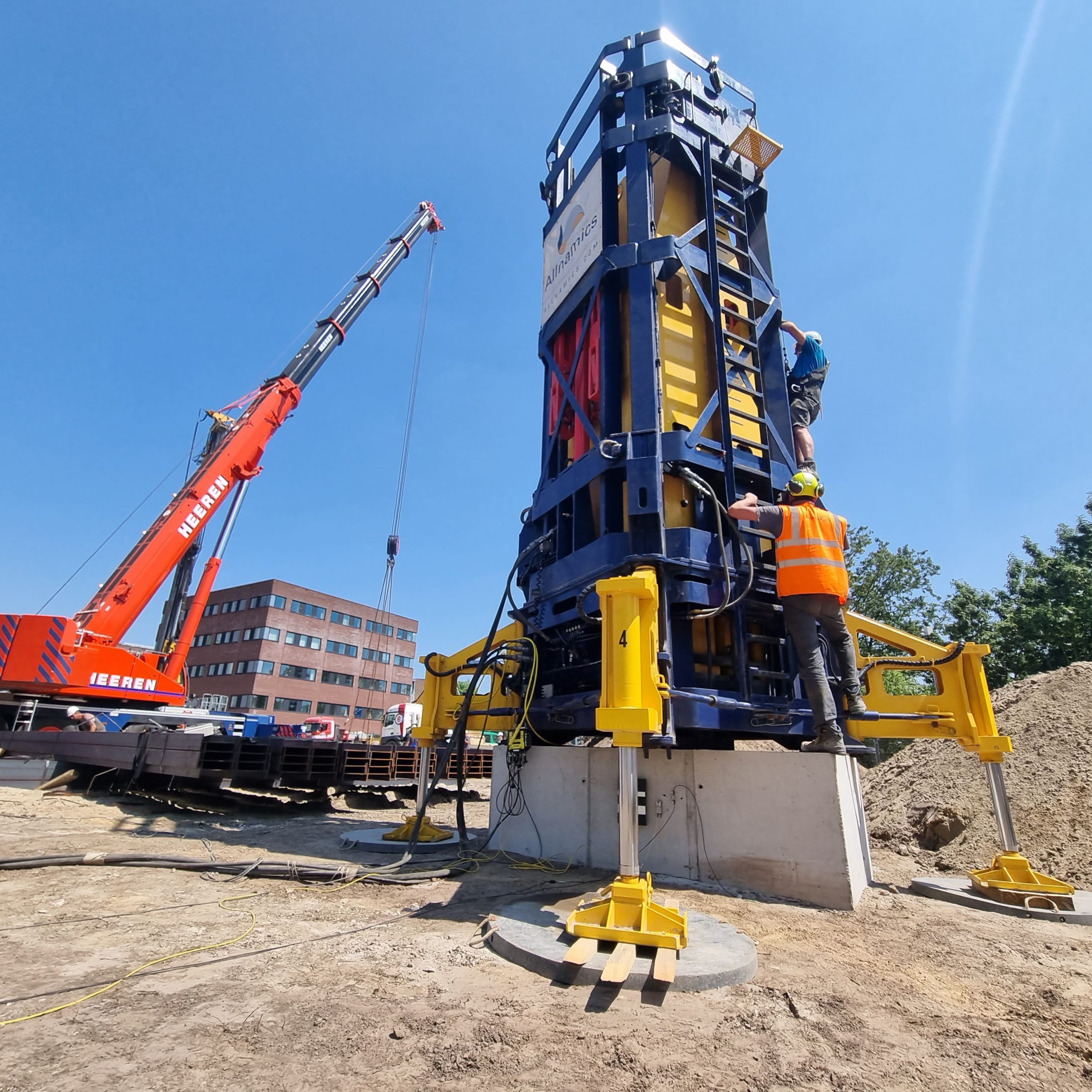
- Rapid Load Testing: Where dynamic testing alone does not capture the full soil response, our StatRapid and Statnamic systems provide a direct measurement of load and settlement under a controlled impulse, significantly increasing the accuracy of capacity determination.
- Independent review and second opinions: If your team needs an independent assessment of monitoring data, signal matching results, or installation records, our engineers provide technically rigorous reviews that stand up to regulatory and contractual scrutiny.
If your project involves offshore pile installation and you want to make sure your monitoring program gives you the data quality and engineering insight you need, contact our team to discuss requirements for your specific project.