Shaft friction and base resistance are the two mechanisms by which a pile transfers load from a structure into the surrounding ground. Shaft friction acts along the pile’s surface as soil grips the pile shaft, while base resistance acts at the pile tip, where the pile bears directly against the soil or rock below. The balance between these two components depends on pile geometry, installation method, and soil conditions — and understanding that balance shapes every pile design decision.
The sections below unpack how each mechanism works, what controls it, and why the distinction matters for pile testing and design.
How do piles actually transfer load to the ground?
A pile transfers load to the ground through two parallel mechanisms: shaft friction (also called skin friction or shaft resistance) and base resistance (also called toe resistance or end bearing). When a structural load is applied at the pile head, the pile attempts to move downward. As it does, the soil surrounding the shaft resists that movement through friction and adhesion along the pile surface. Simultaneously, the soil or rock beneath the pile tip pushes back against the pile toe.
The total bearing capacity of a pile is the sum of these two contributions. In practice, the split between shaft and base varies enormously. A long, slender pile driven into layered sand may derive most of its capacity from shaft friction distributed along its length. A shorter, large-diameter pile bearing on rock may rely almost entirely on base resistance at its toe. Neither mechanism is inherently superior — the right balance depends on the specific project conditions.
This distinction matters beyond design. When a pile is loaded during a pile load test, the way load is distributed between shaft and toe tells engineers whether the pile is performing as designed and whether the soil model used in design reflects reality.
What factors control how much shaft friction a pile develops?
Shaft friction depends on the contact area between the pile and the soil, the roughness or texture of the pile surface, the normal stress acting on that surface, and the shear strength of the surrounding soil. A longer pile with a larger perimeter develops more shaft friction than a short, narrow one — all else being equal. But geometry is only part of the story.
Soil type plays a major role. In granular soils such as sand and gravel, shaft friction is governed by the effective horizontal stress acting on the pile surface and the friction angle between the pile material and soil. In cohesive soils such as clay, shaft friction is more closely related to the undrained shear strength of the soil and the adhesion factor between the pile and the clay.
Installation method also has a significant effect. Driven piles displace and densify the surrounding soil, which tends to increase horizontal stress and improve shaft friction in granular soils. Bored piles, by contrast, relieve stress during excavation and may reduce horizontal stress, which can lower shaft friction compared to a driven pile of the same dimensions in the same soil. The pile material and surface finish matter too — a rough concrete surface develops more friction than a smooth steel tube in the same soil.
Time after installation is another factor, particularly for driven piles in clay. Driving generates excess pore water pressures that temporarily reduce effective stress and shaft friction. As those pressures dissipate over days or weeks, soil resistance recovers — a phenomenon known as pile setup. This is why pile load tests on driven piles are typically conducted after a waiting period, to allow the pile to reach its long-term capacity.
What determines the base resistance of a pile?
Base resistance is controlled by the bearing capacity of the soil or rock directly beneath the pile tip, the cross-sectional area of the pile toe, and the amount of displacement required to mobilize that resistance. A pile with a larger toe area bearing on dense sand or rock will develop substantially more base resistance than a narrow pile with its toe in soft clay.
The soil conditions at the pile toe are the dominant factor. Hard rock, dense gravel, and compacted sand provide high base resistance. Soft clay, loose fill, and organic soils provide very little. This is why pile design in weak soils often relies on driving piles through soft layers to reach a competent bearing stratum below — the goal is to position the toe where base resistance is meaningful.
Pile type also matters. Open-ended steel tubes, such as those used for offshore foundations, may partially plug with soil during driving. Whether the pile behaves as a plugged or unplugged section affects the effective toe area and therefore the base resistance that can be mobilized. Closed-ended piles and solid precast concrete piles have a defined, fixed toe area and develop base resistance more predictably.
One important characteristic of base resistance is that it requires relatively large displacement to fully mobilize — typically several percent of the pile diameter. This is significantly more movement than shaft friction requires, which has important implications for how the two components interact under load.
Which component — shaft friction or base resistance — mobilizes first?
Shaft friction mobilizes first. As a pile is loaded and begins to settle, the soil along the shaft starts resisting movement almost immediately, at very small displacements. Base resistance, by contrast, requires considerably more pile head movement before it fully activates. This sequential mobilization is one of the most important behavioral characteristics of piles under load.
In practical terms, this means that at working load levels — loads well below the pile’s ultimate capacity — shaft friction typically carries the majority of the applied load. The pile toe may contribute relatively little until the pile has settled enough to engage the soil beneath it. For long friction piles, the toe may contribute almost nothing at service loads.
This sequence has direct implications for pile design and testing. A load-settlement curve from a static load test will often show a relatively stiff initial response as shaft friction engages, followed by a softer, more progressive response as the pile continues to settle and base resistance begins to contribute. If the pile is not loaded to sufficient displacement during testing, the base resistance component may not be fully captured.
It also explains why friction piles and end-bearing piles behave so differently under load. A pile designed primarily for shaft friction may reach its capacity at modest settlement. An end-bearing pile may show more settlement before its full capacity is realized, because the toe needs to compress the soil beneath it before maximum resistance develops.
How do pile testing methods measure shaft friction and base resistance separately?
Separating shaft friction from base resistance during a pile load test requires either embedded instrumentation along the pile shaft or signal matching analysis that models the soil resistance distribution. Without instrumentation, a standard pile load test measures only the total capacity at the pile head — it cannot directly distinguish how much comes from the shaft and how much from the toe.
Instrumented static load testing
In an instrumented static load test, strain gauges or load cells are installed at multiple levels along the pile shaft before installation. As load is applied at the pile head, the instruments measure the load at each level. The difference in load between successive gauge levels represents the shaft friction acting over that segment of pile. The load remaining at the deepest gauge level, close to the pile toe, represents the base resistance contribution.
This approach gives engineers a direct, level-by-level picture of load transfer. It is particularly useful for large-diameter bored piles, where the distribution of resistance between shaft and toe is difficult to predict from soil investigation data alone, and where the design may depend on understanding that distribution accurately.
Signal matching in dynamic and rapid load testing
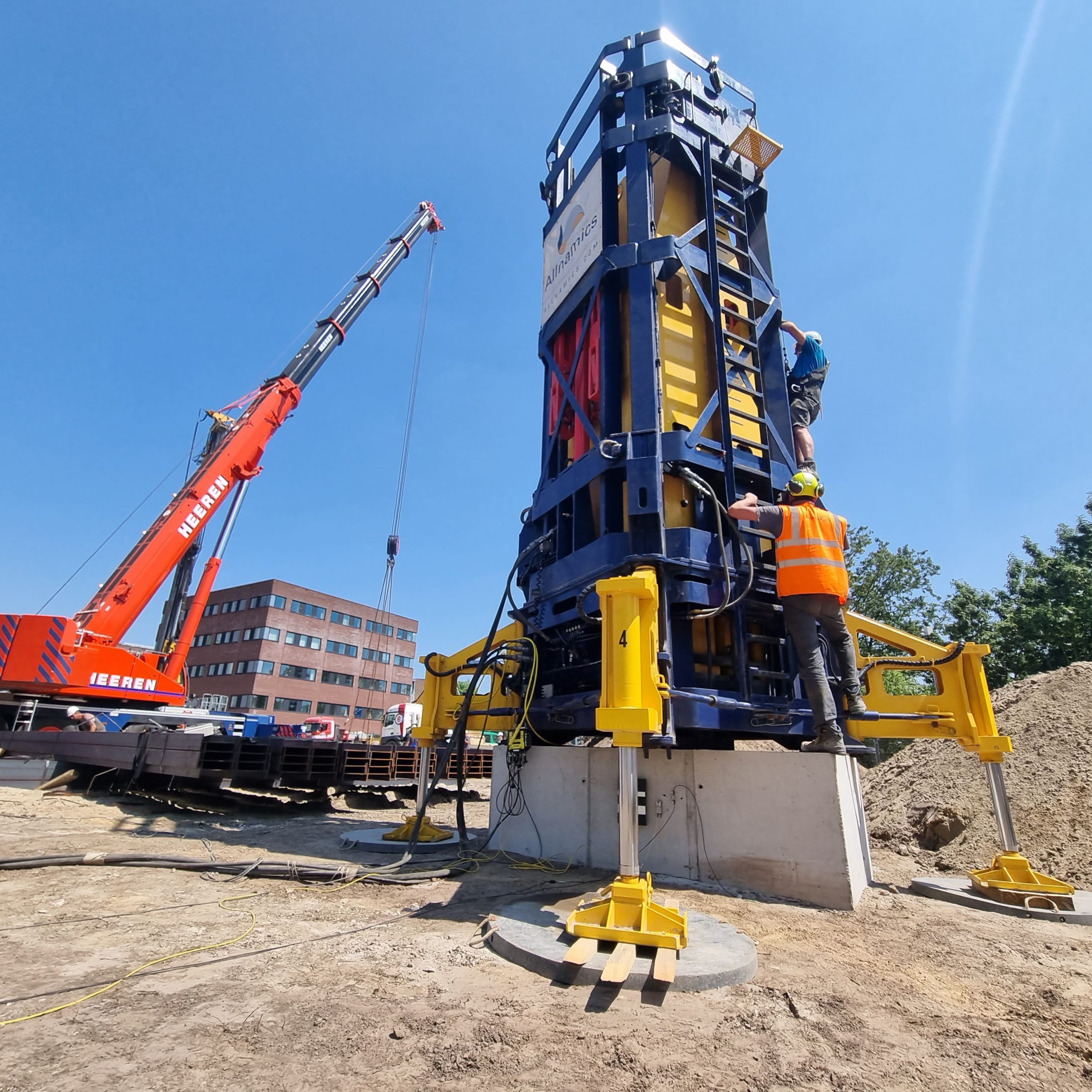
Dynamic Load Testing and Rapid Load Testing derive shaft and base resistance through signal matching analysis. In this process, a soil model is built and adjusted until the calculated pile response matches the measured signals from sensors attached to the pile. The resulting model includes a resistance distribution along the shaft and at the toe, which engineers can extract and interpret.
Signal matching is less direct than embedded instrumentation, but it is far more practical for large programs where instrumenting every pile is not feasible. The accuracy of the separation between shaft and base depends on pile type, soil conditions, and the quality of the analysis. For driven steel piles in granular soils, signal matching produces reliable results. For bored piles or piles in cohesive soils, the separation is less certain and should be interpreted with appropriate caution.
When should a pile design rely more on shaft friction than base resistance?
A pile design should lean toward shaft friction when the pile is long relative to its diameter, when the soil profile offers good friction along the shaft but weak or uncertain conditions at depth, or when settlement control is a priority. Shaft friction distributes load over a large surface area, which tends to produce more uniform, predictable settlement behavior than concentrating load at the toe.
Long bored piles in layered soil profiles — common in urban construction and infrastructure projects — often develop most of their capacity through shaft friction by necessity. The soil at depth may not be strong enough to provide meaningful base resistance, or the pile length needed to reach a competent bearing layer may be impractical. In these cases, the design relies on accumulating shaft friction across multiple soil layers.
Tension piles, used to resist uplift forces in structures such as offshore platforms, anchored retaining walls, and wind turbine foundations, can only rely on shaft friction. Base resistance is a compression mechanism and contributes nothing when the pile is being pulled upward. For tension applications, maximizing shaft friction through pile length, surface texture, and soil selection is the only available strategy.
End-bearing designs are preferred when a strong, stiff bearing stratum is accessible at a reasonable depth, when settlement must be minimized, or when the pile diameter is large enough that the toe area alone can carry the required load. Offshore monopiles for wind turbines, for example, are large-diameter structures where both shaft friction and base resistance contribute, but the design is carefully calibrated to the specific soil layering at each location.
The choice is rarely absolute. Most pile designs rely on both mechanisms to some degree, and the goal is to understand and verify the actual distribution — which is precisely where pile load testing provides its most useful data.
How Allnamics Helps You Understand Load Transfer in Your Piles
Understanding whether your piles are performing as designed — and how load is actually distributed between shaft and toe — requires more than a soil investigation report. We provide the testing, instrumentation, and analysis needed to verify load transfer behavior directly, on your specific piles, in your actual site conditions.
Here is what we can do for your project:
- Instrumented Static Load Testing: We design and execute static load tests with embedded strain gauges or load cells at multiple shaft levels, giving you a direct, level-by-level picture of shaft friction and base resistance mobilization.
- Dynamic Load Testing with signal matching: Using our own PDA system and AllWave-DLT software, our engineers perform signal matching analysis to derive resistance distribution along the shaft and at the toe — practical for large programs where full instrumentation of every pile is not feasible.
- Rapid Load Testing (StatRapid / Statnamic): Where dynamic testing alone does not capture the full soil response, Rapid Load Testing provides a more direct measurement of pile capacity with reduced stress wave effects — useful for bored piles and piles in cohesive soils where shaft friction behavior is complex.
- Independent technical review and design verification: We review your pile design assumptions, assess whether the predicted shaft friction and base resistance values are supported by the available soil data, and recommend a testing program that gives you the evidence you need to proceed with confidence.
- Offshore foundation testing: For offshore wind, oil and gas, and marine infrastructure projects, we provide specialized testing and monitoring services that verify load transfer in environments where remediation is costly and access is limited.
If you want to verify how your piles are actually transferring load to the ground, contact our team to discuss a testing approach matched to your pile type, soil conditions, and project requirements.