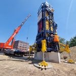
How does the PDR data logger work during pile driving?
The PDR data logger records strain and acceleration measurements at the pile head during every hammer blow, capturing the force and velocity signals that form the basis of pile driving analysis. It processes these signals onboard and transmits them wirelessly in real time, giving engineers immediate visibility into pile behavior, driving stresses, and installation quality without requiring a wired connection to a separate control unit. The sections below unpack how each part of that process works, what the data reveals, and when the PDR is the right tool for the job.
What data does the PDR data logger actually record during pile driving?
The PDR data logger records strain and acceleration at the pile head during each hammer impact. Strain sensors measure the compressive and tensile forces traveling through the pile as a stress wave, while accelerometers capture the velocity of the pile head motion. Together, these two signals allow engineers to derive force and velocity time histories for every blow in the driving sequence.
Beyond those two primary channels, the PDR system supports a broader set of measurements depending on the sensor configuration used. During a typical pile driving monitoring session, the data logger can record:
- Compressive and tensile stresses at the measurement cross-section
- Pile head velocity derived from accelerometer output
- Pile set per blow, expressed both in absolute terms and as penetration rate over time
- Hammer performance indicators, including blow rate and transferred energy
- Fatigue contribution of each blow to the pile material, which is particularly relevant for steel piles on offshore projects
When the PDR is used during vibratory driving rather than impact driving, it switches to monitoring continuous vibration parameters: hammer frequency, pile penetration as a function of time, and the cyclic stress amplitudes that contribute to material fatigue. This makes the PDR useful across both installation methods, not just conventional impact-driven piles.
How does the PDR process and transmit signals in real time?
The PDR processes sensor signals onboard the unit itself, converting raw analog output from strain gauges and accelerometers into calibrated digital data at high sampling rates. It then transmits that processed data wirelessly to a receiving device, typically a laptop or tablet operated by the engineer on the installation vessel or at the site office, so results appear on screen within moments of each hammer blow.
The wireless transmission relies on a Wi-Fi connection between the PDR unit mounted on the pile and the engineer’s workstation. For offshore applications or situations where the pile is at a significant distance from the control point, an external Wi-Fi antenna extends the reliable communication range. This removes the need for long signal cables running from the pile to the monitoring station, which is a practical advantage on busy installation decks and in offshore environments where cable management creates safety and logistical complications.
The onboard processing architecture means the PDR does not simply relay raw sensor voltages. It applies the sensor calibration factors, performs the necessary unit conversions, and outputs force and velocity traces that are ready for immediate review. Engineers can assess driving stresses, transferred energy, and set per blow in real time, allowing them to intervene if parameters move outside acceptable limits during the installation itself rather than discovering problems after the fact.
What is the difference between the PDR and a conventional PDA system?
The key distinction is that the PDR is a compact, wireless, self-contained data acquisition unit, while a conventional Pile Driving Analyzer (PDA) system typically consists of a separate control box connected to sensors by cables, with processing and display handled on a dedicated unit that must remain physically close to the pile. The PDR integrates acquisition, processing, and wireless transmission into a single device that mounts directly on the pile.
In practical terms, this difference matters most in three areas:
- Mobility and setup time: The PDR requires no signal cables between the pile and the engineer’s workstation, which simplifies installation and reduces setup time on congested construction sites and offshore decks.
- Offshore and underwater capability: The PDR system has been developed specifically with offshore monitoring in mind. Sensors certified as waterproof to depths of up to 500 metres can be paired with the PDR, making it suitable for underwater pile monitoring where conventional cable-based systems face significant practical limitations.
- Scalability: The Quad PDR configuration allows up to 16 channels to be monitored simultaneously, supporting instrumentation programs that require measurements at multiple cross-sections or on multiple piles within the same installation sequence.
Both the PDR and conventional PDA systems ultimately serve the same analytical purpose: capturing the force and velocity data needed for pile driving analysis and signal matching. The difference lies in how that data is collected and delivered, and the PDR’s architecture makes it better suited to demanding field conditions, particularly offshore.
How is the PDR installed and set up on a pile?
The PDR and its sensors are mounted directly on the pile shaft, typically near the pile head, before driving begins. Strain sensors and accelerometers are attached to the pile surface at the measurement cross-section, and the PDR data acquisition unit is secured to the pile in a position where it can communicate wirelessly with the engineer’s receiving device.
The setup process follows a structured sequence to ensure data quality from the first blow:
- Sensor attachment: Strain gauges and accelerometers are fixed to the pile at the designated cross-section, positioned symmetrically to capture representative measurements and cancel out bending effects.
- PDR unit mounting: The data logger is secured to the pile, connected to the sensors via short local cables. The unit’s position is chosen to keep it clear of hammer impact zones and to maintain line-of-sight or near-line-of-sight to the Wi-Fi receiver.
- Calibration verification: Sensor calibration factors are entered or confirmed in the system. A test box is available for checking the PDR system and sensors before deployment, which reduces the risk of discovering a sensor fault after the pile is already in position.
- Wireless link establishment: The connection between the PDR and the engineer’s workstation is confirmed. If the distance or site conditions require it, an external antenna is deployed to extend the Wi-Fi range.
- Pre-drive checks: The engineer reviews the live signal feed during initial low-energy blows to confirm that all channels are responding correctly before full driving energy is applied.
For underwater applications, the sensors used are rated for the relevant water depth, and the PDR system is configured accordingly before the pile is lowered into position. Once driving begins, no further physical access to the sensors is required.
What can PDR data reveal about pile integrity and bearing capacity?
PDR data reveals driving stresses, transferred hammer energy, and the force-velocity relationship at the pile head for every blow. From this information, engineers can assess whether the pile is sustaining damaging stress levels during installation, estimate the soil resistance being mobilized at the time of driving, and identify anomalies in the signal that may indicate structural damage or changes in pile cross-section.
Pile integrity indicators
During driving, the stress wave travels down the pile and reflects back to the sensors. The shape and timing of that reflection carry information about the pile’s structural condition. A clean, consistent reflection pattern indicates a uniform pile cross-section. Unexpected reflections arriving too early, or with unusual amplitude, can signal a crack, a joint defect, or a reduction in cross-section that warrants further investigation.
Monitoring tensile stresses is equally important. Excessive tensile stress during driving, particularly in concrete piles, can cause cracking that is not visible from the surface. Real-time PDR data allows the installation team to adjust hammer energy or driving sequence before tensile stress levels reach a damaging threshold.
Bearing capacity estimation
The force and velocity data recorded by the PDR during driving provide the input for signal matching analysis using software such as AllWave-DLT. This analysis derives a soil model that estimates the distribution of soil resistance along the pile shaft and at the toe, from which bearing capacity can be inferred. For the most reliable capacity assessment, this analysis is performed on data recorded during a redrive, after the soil has had time to set up around the pile, because the static bearing capacity increases with time following initial installation.
It is worth noting that signal matching results are significantly more reliable than direct methods such as the CASE method applied directly to field data, particularly for piles with variable cross-sections or in cohesive soils where time-dependent behavior plays a role.
When should engineers use the PDR instead of full dynamic load testing?
Engineers should use the PDR for installation monitoring when the primary objective is quality control during driving rather than a formal bearing capacity determination. The PDR is the right tool when you need real-time stress monitoring across a large number of piles, when site conditions make a full dynamic load test setup impractical, or when the project requires continuous data logging throughout the installation program rather than selective testing of individual piles.
Full Dynamic Load Testing for pile capacity involves a more structured test protocol, typically performed during a redrive after soil setup, with the explicit goal of assessing static bearing capacity through signal matching. DLT is the appropriate choice when:
- Formal verification of bearing capacity is required for design confirmation or regulatory compliance
- The project involves a smaller number of piles where individual test results carry significant weight
- Post-installation assessment is needed after a period of soil consolidation
In practice, the PDR and full DLT are often used together on the same project. The PDR monitors every pile during installation, providing continuous quality control data and flagging any piles that show anomalous behavior. A subset of those piles then undergoes a formal DLT redrive to establish bearing capacity with the rigor required for design validation. This combination gives your team both broad coverage across the installation program and defensible capacity data for the piles that matter most.
For offshore programs where access to individual piles after installation is difficult, the PDR’s ability to capture high-quality data during the driving window itself makes it especially valuable. Missing that window means losing the opportunity to gather any direct measurement data at all.
How Allnamics Supports PDR Monitoring and Pile Driving Analysis
We developed the PDR data acquisition unit in-house, and we deploy it across onshore and offshore projects worldwide as part of our pile driving monitoring and dynamic load testing services. Our team supports the full monitoring workflow, from sensor selection and system configuration through to signal matching analysis and reporting.
Here is what working with us on a PDR-based monitoring program looks like in practice:
- System configuration: We select the appropriate sensor types and PDR configuration for your pile type, installation method, and site conditions, including waterproof sensors for offshore and underwater applications.
- On-site monitoring: Our engineers manage the PDR setup, monitor data quality in real time during driving, and intervene immediately if stress levels approach critical thresholds.
- Signal matching analysis: Where bearing capacity assessment is required, we perform signal matching using AllWave-DLT software, elaborated by qualified engineers with direct experience in offshore and onshore pile behavior.
- Vibratory driving monitoring: For piles installed with vibratory hammers, we apply VDM and VDA monitoring protocols that track hammer performance, pile penetration, and fatigue contribution throughout the installation.
- Reporting and recommendations: We deliver clear, actionable reports that your team and project stakeholders can use for design validation, quality records, and risk management decisions.
If you are planning a pile installation program and want to discuss how PDR monitoring fits into your quality control or testing strategy, contact our team directly to talk through the options for your specific project.